Audio multiplexers can be a useful accessory in any shack, and this one is easy to build for around $30 from readily available parts. All of the parts used in this project were sourced on Amazon.
The MUX described in this article will become part of a homebrew QRP SSB transceiver. The MOSFET MUX switches are borrowed from the webpages[1] of Rick, N3FJZ, but the selection logic is my own. N3FJZ has a large YouTube presence[2], too. Please visit both.
This device has a single input and four outputs. Since the MUX is bidirectional, one of two signals may flow towards the balanced modulator input upon transmit, and the product detector output may flow towards one of two outputs upon receive, i.e., two of the four channels are used for transmit and two of the four channels are used for receive.
The MUX has four modes of operation. Two are available upon receive, and two are available upon transmit. This design is expandable to more channels, but four is the practical limit for the CD4072 OR- gates used. For more channels, a microcontroller like an Arduino, or Raspberry Pi becomes more practical. An intermediate solution might be some sort of programmable logic array (PLA).
My specific application for this multiplexer is described in the sections that follow, but the same circuit may be used, bidirectionally, for small signals in most any audio application.
Upon Receive
1. Normal Discrete Audio Amplifier Path
This path employs a discrete audio amplifier to amplify the output of the SSB product detector which passes through one channel of the MUX. The output is available to a loudspeaker or headphones.
2. Leveled Audio Path
This path employs a dedicated, discrete audio amplifier to amplify the output of the SSB product detector that passes through one channel of the MUX. It supplies audio power to the W2AEW audio leveler circuit[3]. Alan Wolke has an enormous YouTube presence and following, too. His circuit is used to mitigate QSB fades from audio. The leveled output is of the order of 50 mV and must be amplified further. The leveled output is further amplified by the discrete audio amplifier of 1, above, before be being made available to a loudspeaker or headphones.
Upon Transmit
3. Microphone Preamplifier Path
This MUX path routes the output of a discrete microphone preamplifier through the MUX and to the input of the SSB balanced modulator.
4. Microphone Compressor Module Path
This path routes the microphone output to the input of an Analog Devices SSM2167 Low Voltage Microphone Preamplifier with Variable Compression and Noise Gating[4]. The output of the SSM2167 compressor module is routed to the input of the SSB balanced modulator. These modules are readily available on eBay[5] or Amazon[6]. There now appear to be two versions of the module; one with electret microphone bias and one without. The one being used for my application is the one without. Bias for my electret microphone is provided on my PCB. Please check the values of the compression ratio and noise gate resistors prior to using the module. They have been known to be reversed on some earlier versions of the module not having the electret microphone bias feature. My modules, purchased on Amazon, were alright.
How It Works
Referring to the top of the schematic in Figure 1, there are two lines labeled “From Audio Leveler IN/OUT Toggle Switch” and “From Compressor IN/OUT Toggle Switch.” The former toggle switch, located on the radio front panel, asserts its commands upon receive, while the latter toggle switch, also located on the front panel, asserts its commands upon transmit.
Upon receive, the control panel Audio Leveler Toggle Switch when in its OFF state will call up 1, as described above. When the same switch is in its ON state (grounded), it will call up 2, as described above.
Upon transmit, the control panel Compressor Toggle Switch when in its OFF state will call up 3, as described above. When the same switch is in its ON state (grounded), it will call up 4, as described above.
There is a 2-relay module in the schematic. The relay to the left (not delineated) functions upon transmit while the relay to the right (not delineated) functions upon receive. Each relay has normally open (NO) contacts and normally closed (NC) contacts. Thus, there are 4 contact positions in total.
From the schematic, it may be seen that the +12V_TX voltage, a voltage only asserted upon transmit, will be placed on the pole of the left relay. Whether this voltage is applied to the NC contacts for the MIC or the NO contacts for the COMPRESSOR will depend upon the state of the corresponding front panel toggle switch.
From the schematic, it may be seen that the +12V_RX voltage, a voltage only asserted upon receive, will be placed on the pole of the right relay. Whether this voltage is applied to the NC contacts of the DISCRETE AMP or the NO contacts for the LEVELER will depend upon the state of the corresponding front panel toggle switch.
The inputs to the CD4072 4-input OR gates in the schematic are hard wired as shown according to the Truth Table. Any time there is a wire connected to a gate input, it signifies a logic HI input. If there appears to be a gate input skipped, that means that logic LO is signified. Since only one of the vertical “wires” can have voltage on it at a time, each of the vertical wires, with its attendant gate connections, constitutes a logic state. This is what is called a “finite state machine” which is a big word for one, or more, hardwired programs. An OR gate functions such that there will be a logic HI output whenever there is at least one logic HI input. Else, the output is logic LO.
The MUX is implemented with 2N7000 MOSFETs used as SPST switches. Each of MOSFETS is driven from the output of an OR gate. The MOSFET will be ON whenever the output of an OR gate is in a logic HI state and OFF whenever the output of an OR gate is in a logic LO state. Each of the channels employs two MOSFETS; one in series and one in shunt connection. When a channel is unused, the series MOSFET will be OFF while the shunt MOSFET will be shorted (ON) to ground. That helps to ensure that the channel is really off. In reality that won’t happen because the MOSFETS have a finite (very high) OFF resistance and a finite (very low ON resistance). What is hoped is that the signal isolation will be good enough for most applications. As a matter of note, there are MOSFETs with lower ON resistances, but those tend to be MOSFETs with larger gate areas. Those devices tend to switch more slowly because of higher gate capacitance.
Four connections to the MUX are shown at J3, J4, J5 and J6 at the top of the schematic. J3 and J4 serve as inputs upon transmit only, while J4 and J5 serve as outputs upon receive only. Connector RF1 serves as the connection to the mixer that, upon transmit, functions as the balanced modulator while, upon receive, the same mixer functions as the product detector.
Component numbering on the printed circuit board, Figure 2, differs from the numbering on the schematic because Figure 1 was prepared prior to the board layout. The circuit wiring is the same, though.
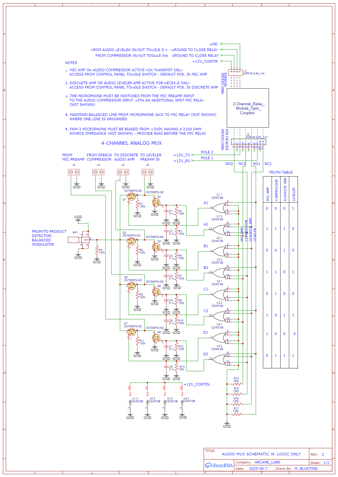
Figure 1. 4-Channel Audio Multiplexer. The MUX is driven by an array of 8 x 4-input OR gates that function to decode each of 4 logic states. For operation of this primitive “state machine” please refer to the text. Please click on the figure to open it in a new window.
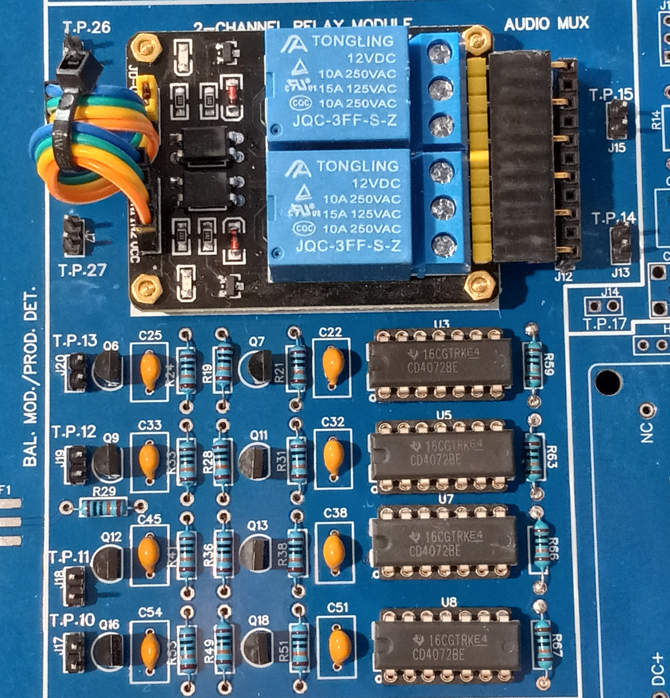 Figure 2. 4-Channel Audio Multiplexer PCB Under Assembly. This MUX is but a small portion of a much larger printed circuit board that contains all of the audio functions described in this article, namely receiver audio amplification, audio leveling, microphone audio amplification, and microphone audio compression. The small pads to the left of the photo are for an SMA connector that connects the MUX to a mixer that serves as a product detector upon receive and a balanced modulator upon transmit. The 2 x 4-input CD4072 CMOS OR gates (8 OR gates in all) to the right are configured to decode four logic states; two for receive and two for transmit. All transistors are 2N7000, all resistors are 100k ohm, and all capacitors are 0.1 uF. A two-channel relay is pictured. The upper relay is active upon receive, while the lower relay is active upon transmit. Please click on the photo to open it in a new window.
Board Design
The printed circuit board was designed using EasyEDA[7], an easy-to-learn online design tool. The boards were fabricated from a Gerber file sent to JLCPCB[8]. Turnaround time was less than one week including UPS shipping.
References
[1] http://www.remmepark.com/circuit6040/
[2]https://www.youtube.com/@Circuit6040/videos
[3]https://www.youtube.com/watch?v=1h0FZJYXQ_w&t=67s
[4]https://www.analog.com/en/products/ssm2167.html
[5]https://www.ebay.com/sch/i.html?_nkw=SSM2167&_sacat=0&_from=R40&_trksid=p4432023.m570.l1313
[6] https://www.amazon.com/s?k=ssm2167&ref=nav_bb_sb