Tag Archives: Homebrew

Hands-On Yagi Antenna Construction 2.0 for Teaching and Experimentation

The most important piece of equipment in ham radio is our antenna.  We are connected to the world with the magic of radio waves!  Each License Exam from Technician through Extra class has questions to test our knowledge on antenna design and building skills.  Home-brewed antennas are easy and relatively inexpensive projects.

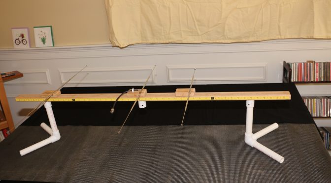
This article describes a 2m, 3-element Yagi antenna construction concept that the N1FD FCC license teaching team has used over the last year for class demonstrations.  The “Lego” style construction (v. 2.0) shown in the above picture is our new design that demonstrates the operating principles of the ubiquitous basic dipole antenna as well as a 2-meter, 3 element Yagi.  (Note, This project evolved from an earlier effort by Diana Eng at Makezine.com, which can be seen here.

In this Newsletter issue, we will describe the construction of the “Lego” stylized antenna and show how it can illustrate basic properties of a dipole antenna.  We will build a Yagi antenna with the addition of reflector and director arms in a future Newsletter article.

CONSTRUCTION of the LEGO STYLIZED ANTENNA.
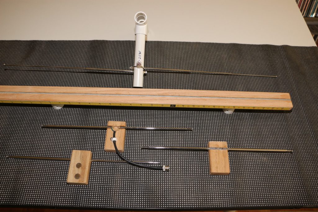
Yagi Antenna - Lego Antenna Parts and Receiver Antenna
Lego Antenna Parts and Receiver Antenna

The antenna demonstration unit consists of two assemblies. 

  1. A handheld receiver dipole set to a fixed frequency (e.g., 146.550 MHz). It is shown at the top of the photo above. It follows a “plumber’s delight” construction using pieces of PVC pipe for a short boom and handles.  The dipole arms are two telescoping (7-28 inch) FM radio replacement antennas, available on eBay or Radio Shack ($4-6 dollars).  The arms feed through the boom and are epoxied.  Bridging across the arms is a common 6-volt flashlight bulb.  The bulb lights up when the dipole receives a resonant rf signal.
  1. The “Lego stylized” Yagi antenna components are shown below the receiver unit. The boom (middle item) is made of red oak dimensioned at ¾  x  1 ½   x  48    The top surface is grooved to hold an epoxied  3/16  steel rod.  The bottom surface has drilled recesses to fit ¾ in PVC pipe for leg stands. The edge of the boom has two 24-inch adhesive tape rulers running from center to front and back of the boom.  The rulers read-out the spacing between the driven dipole element and the parasitic reflector and director arms. In the photo, the D.E. and parasitic elements are seen below the 48 in. boom.  The center element is the driven dipole and it is flanked by identical units that can be configured as either reflectors or directors.   Each unit consists of two telescoping FM radio antenna rods epoxied in a grooved piece of red oak ( ¾  x  1 ½  x  3 inches) serving as “riders” on the boom.  The telescope arms can be adjusted to “resonance” at any frequency in the 2-meter band. The bottom of all riders has 2 x ½ inch rare earth magnets.  These allow the three antenna elements to be fixed at any position on the 48 in. boom.

You can view a closer look at the assembled Yagi antenna configuration in this video (Click on Link)

DEMONSTRATIONS OF BASIC DIPOLE BEHAVIOR. 

1.  Antenna Resonance Determined by Dipole Length.

As we all know, the resonance length of a dipole is given by the equation:    L (in inches)  =  5616/ [ Frequency (in MHz)].  We can show this fact with aid of the “receiver” antenna, which is set for a frequency of 146.55 MHz  The light bulb of this antenna will light when it senses a signal of this value from our “Lego” antenna.

In the video below (Click on Link), we begin with a resonant D.E. length of 38.5 inches and see the receiver antenna light up.  Next, we manually shorten the D.E. and see the bulb light dramatically dim.  When the D.E. length is returned near the start value, the light bulb again brightens up.

  1. Effect of SWR on Signal Strength.

Most modern transceivers have a built-in auto-tuner that can match SWR up to 3:1.  We know this only makes the “radio happy”, still we key down without much thought on how our Tx signal degrades with a 3:1 match.  The pictures below use the transmitting “Lego” dipole and receiver dipole to show the received signals for an SWR of 1.1 and 3.0.  The SWR was changed by lengthening the D.E. elements by 2 inches while holding the Tx frequency at 146.55 MHz
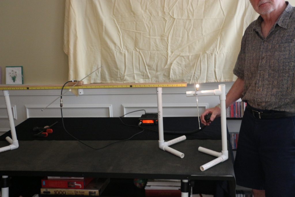
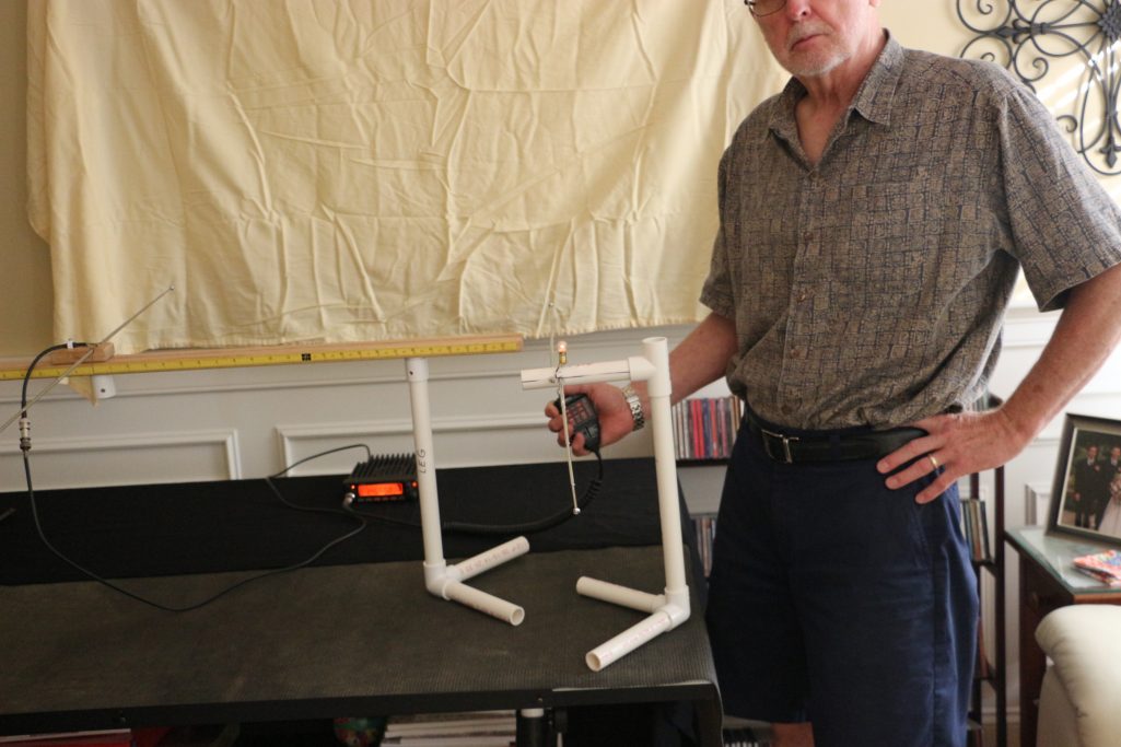
Yagi Antenna - Receiver Signal-for Lego Dipole SWR 1.1
Receiver Signal-for Lego Dipole SWR 1.1
Yagi Antenna - Receiver Signal- for Lego Dipole SWR 3.0
Receiver Signal- for Lego Dipole SWR 3.0
3.  Polarization Effects between Tx and Rx Antennas.

A horizontal dipole shows “horizontal” polarization; meaning the electric field vector of the rf signal is parallel to the earth surface.  Similarly, a vertical dipole displays “vertical” polarization with the electric field perpendicular to the earth. We all learn this in a Technician class course.

When we use our 2m HT’s for short distance contacts, Tx and Rx antennas with opposite orientation create a huge signal loss.  The effect is shown dramatically in the video below.

CONCLUSION 

Our classroom constructible antenna for demonstrations in our Ham Radio license classes has evolved in design over the past year.  We believe it has been a useful resource,  helping students translate textbook theory to “Hands On” practice.  Perhaps, this review has kindled interest for our readers to think of their Next Antenna Project!

73 & Hope to hear you on the air,

Dave N1RF

Plans for N1FD Field Day 2016

Field Day Planning Team

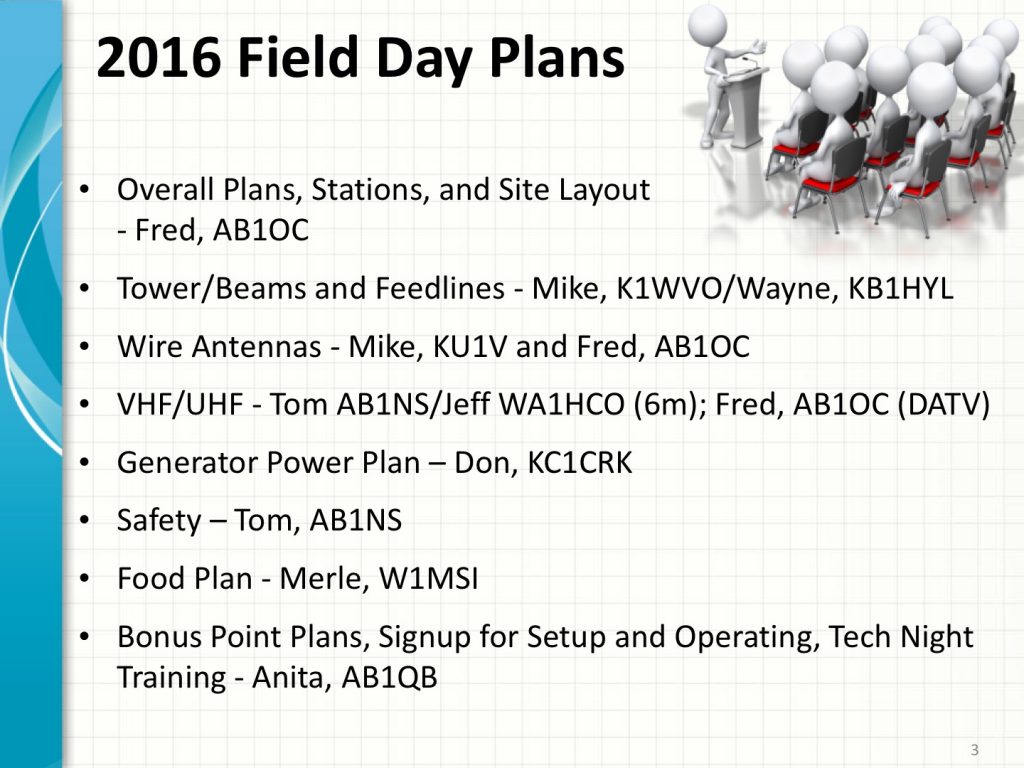
Our 2016 Field Day Operation is rapidly approaching and our planning is in high gear! We have a great planning team working on Field Day this year and we have a lot of fun planned!

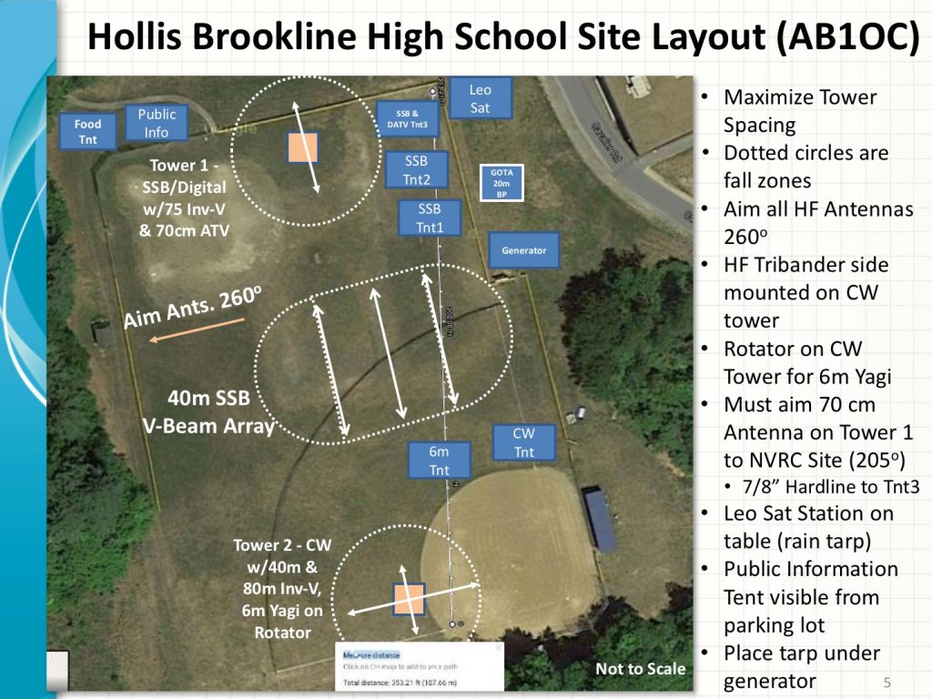
Field Day Planning - Site Layout at Hollis-Brookline High School
Site Layout at Hollis-Brookline High School

We will be operating at the Hollis-Brookline High School in Hollis, NH this year. We’ve been working on antenna plans and a layout for the site. We expect to be 7A or 8A this year. We are also going to try operating using a combination of Digital and SSB Phone from the SSB Stations.

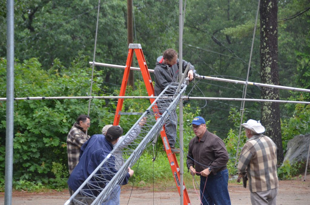
Falling Derrick Tower and Beams

We will have two towers with Tri-band Yagis for 20m, 15m and 10m and Inverted-V antennas for 80m/75m. We will be using triplexers and bandpass filters to allow the Tri-band Yagis to be shared across three transceivers as we did last year.

One tower will be used for CW operations as well as supporting the club’s 4 Element, 6m Yagi. The 6m Yagi will be rotatable. Jeff, WA1HCO and Tom, AB1NS have some cool plans for the 6m station this year which include Meteor Scatter and Es Contacts if we can catch openings on 6m. The CW tower will also have a 40m Inverted-V Antenna.

The other tower will be used to support the SSB/Digital stations on 75m, 20m, 15m, and 10m as well as an 11 Element Yagi for 70cm (more on this below).

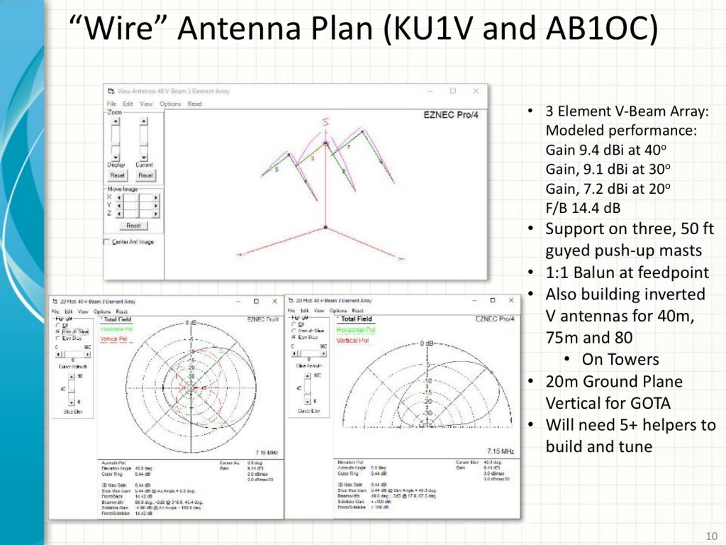
Field Day Planning - 40m 3 Element V-Beam
40m 3 Element V-Beam Plans

We are planning some new antenna and station projects for our 2016 Field Day operation. We are going to build a 3 Element, 40m V-Beam Array using three 50 ft guyed masts. This antenna should perform comparably to a 40m short 2 Element Yagi at 70 ft.

Digital ATV Demonstration on 70cm

We are also planning a Digital Fast Scan ATV link between our Field Day site and the Nashoba Valley Club’s site. This will allow us to send and receive Live Digital Video between the two sites on the 70cm band.

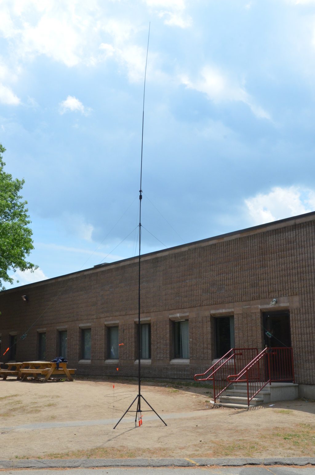
20m Buddipole Ground Plane Antenna for GOTA Station

Wayne, KB1HYL will be operating the GOTA Station again this year. We are going to put the GOTA station on 20m using a Ground Plane Vertical Antenna built from Buddipole Kit.

Club Meeting About Field Day Planning
Club Meeting About Field Day

Our Field Day Planning team is planning a great presentation on Field Day 2016 at our next Club Meeting on June 7th and our Tech Night on June 14th will be all about the Technical Side of Field Day – Building Antennas, Setting Towers and Stations, Loggers, Digital Modes and much more. Don’t miss these!

QRZ  Number  1  Field  Day ?

Fred (Field Day Incident Commander, N1FD)

Hashtags: #ARRL 

A Stealth Antenna Farm

Living in a community that expressly prohibits ham radio towers often means enduring constant frustration trying to work DX with wire antennas or a multi-band vertical with what is always an inadequate radial field (read: less than 200 radials) over the “worse soil in the world”. My mantra of “work ’em on all bands and all modes” that I pursued for many years from my NH QTH has morphed to “hope I can hear them and they can hear me”. My lot can support a 40-foot tower that would be great for a small beam like the Cycle 24 used during the World Radiosport Team Championship a couple of years ago. Unfortunately, I would never get past a permit for the tower base if I ever tried to put one up.

Ah, but there is hope. The frustrations wrought by CC&R limitations often bring out the ingenuity in hams. Thanks to Layne, AE1N, I visited the website of Jeff, AC0C (see AC0C.com). Jeff lived in a condo with the no-tower restrictions. He looked over the attic where he lived and set about figuring out how to build an array of beams using the roof support structure. In a triangular volume measuring 16 feet at the apex, 20 feet long, and 40 feet wide, he managed to cram in a 22-element array that covers 160 – 6 meters! A scan of Jeff’s website is a testament to a ham’s perseverance to build an antenna farm where common sense says you cannot. Jeff used the popular EZNEC modeling program developed and maintained by Roy, W7EL. The overall configuration of the project shown on Jeff’s website looks like the proverbial rat’s nest. Somewhere on his site he mentions using over 1000 feet of coax, hundreds of ferrite cores, dozens of relays, and numerous switching boards to select the desired antenna while holding the RFI beast at bay.

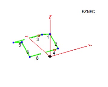
Intrigued by Jeff’s work, I decided to take a look at my garage attic and see what I could do. My attic measures about 17.5 feet long, 19 feet wide, and 5 feet at the center above the floor. There is usable space beyond the garage over the remainder of the house that runs to the back, providing more depth. Unfortunately, my attic runs N-S so that any fixed antenna would have to be situated to favor a pattern to the E/NE direction for DX. I studied Jeff’s design for his 2-element 40 meter Yagi and decided to scale it for 30 meters. Each element resembles an inverted-V with the lower half of the ends bent at right angles to run horizontally along the floor of the attic. The horizontal portions of each element run toward each other so that the antenna resembles a modified “bent” Moxon antenna. (The Moxon antenna owes its design to Les Moxon, G3XN (SK). It is a 2-element beam that resembles a rectangle, is easy to build, and is forgiving in dimensions for a given band.)

I modeled the antenna with a separation of 19 feet between the elements and inserted loading coils in the driven element to shorten them. The apex height of the antenna is only about 14 feet above the ground so I was not expecting spectacular gain in the primary direction (North). The resulting pattern resembled a low dipole with maximum gain of 4.5 dB North and South, dropping to 3.4 dB at 45 degrees. While this may seem respectable, it occurs for an elevation angle of 45 degrees which means it would not work very well for typical DX angles. Indeed, when I looked at the gain performance at 24 degrees elevation, I had less than a dB. (The astute DX’er will notice that good DX performance occurs for elevation angles of 15 – 20 degrees. When limited to a height of 14 feet, the gain profile at 15 degrees is over 8 dB down from its peak.) Figure 1 shows the layout of the antenna. I realized that I’d be better off with a 30-meter inverted-V dipole off the back of the house.

Stealth Antenna– 30-meter 2-element Attic Yagi
Figure 1 – 30-meter 2-element Attic Yagi

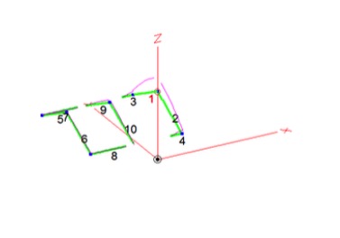
Not to be deterred, I then modeled a 17-meter 2-element beam using relays to disconnect the 30-meter element at its coils and inserting an inverted-V element between the 30-meter elements to act as a director for 17. Figure 2 shows the results where the driven element is on the right and the director is at the center.

Stealth Antenna – 17-meter & 30-meter Attic Yagis
Figure 2 – 17-meter & 30-meter Attic Yagis

The performance for 17 meters was similar to 30 meters with a modified dipole pattern. The gain was a little better at a 24-degree elevation angle but still less than 2 dB. Again, better to stay with my inverted-V that boasts a 3.8 dB gain toward NE.

While I pondered my next move, it occurred to me that what worked for Jeff might not be the best idea for me. All that coax and those ferrite cores pointed to a lot of blood, sweat, and tears to get rid of RFI gremlins that such close quarters tend to foster. I considered using relays to change bands by lengthening or shortening the antenna elements. However, this would mean control cable wires from the shack to the antennas, themselves inadvertent antennas when transmitting. There has to be a better way.

Then, the long-dormant light bulb in my head came on. Why not try a 2-element wire beam? I looked at a model for such a beam for 17 and 15 meters, 2 elements for each band on the same “boom” and each fed separately. The results showed 17 meters behaves as expected with a gain of 6.2 dBi and a F/B of 21.6 dB. However, the 15-meter portion had a peanut-shaped pattern that was reversed from the intended direction with a F/B of less than 5 dB. I adjusted the height of the 15-meter elements within the available limits but to no avail.

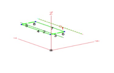
Now what? I looked at the Moxon design again for its space-saving feature to see if I could get more isolation between the beams. I pulled up the file for the 2-element 17-meter beam and another file for a 15-meter Moxon beam. I merged the two antennas and juggled the positions so that the Moxon was a foot above the wire beam. Figure 3 shows the EZNEC model.

Stealth Antenna – 17-meter Beam with 15-meter Moxon Above
Figure 3 – 17-meter Beam with 15-meter Moxon Above

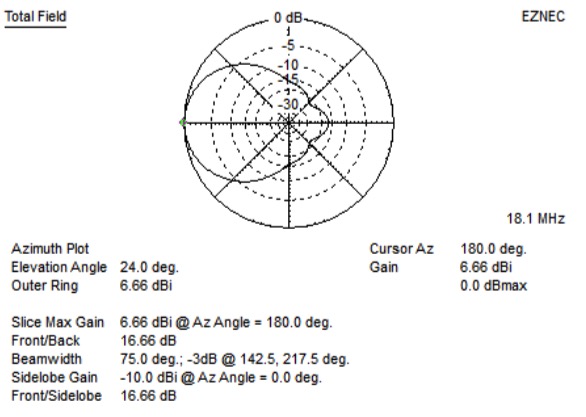
Figure 4 shows the azimuth gain pattern for the 17-meter beam.

Stealth Antenna – 17-meter Beam Pattern (15-meter Moxon Above it)
Figure 4 – 17-meter Beam Pattern (15-meter Moxon Above it)

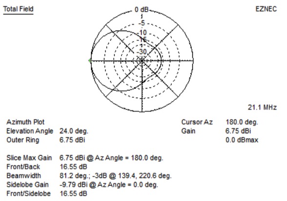
Changing antennas for the 15-meter Moxon antenna produces the pattern shown in Figure 5.

Stealth Antenna – 15-meter Moxon Gain Performance
Figure 5 – 15-meter Moxon Gain Performance

As the model plots suggest, both antennas have nearly identical performance. Success at last! At least on paper minus any interactions and interfering structures such as air conditioning ducts and electrical wiring. Installing two antennas with separate feeds is easy to control with a remote antenna switch. I avoided the need for relays to shorten elements on 17 meters in order to work on 15 meters. I did not want to use relays because of the prospect of RFI causing them to trip, and the need for extra wires from my shack plus ferrite cores for RFI suppression. Now on to the fun part – BUILD IT.

Radio Amateurs Developing Skills Worldwide