Tag Archives: Homebrew

Moxons in the Attic (Part 2)

 It has been a couple of months since I wrote about my project to build a Moxon antenna for 15 and 17 meters in the attic of my garage.  The weather has since cooled down to where I can work in the attic without sweat dripping in my eyes and my hands slipping on everything.  When I wrote about my initial measurements in the last article, I was experiencing erratic SWR readings on the 15-meter beam with the lowest SWR being around 23 MHz.  I did some recomputing and figured I would need to lengthen each element by 24 inches to bring resonance down to 21.1 MHz.  I was not too thrilled with the idea of having to solder wires in the cramped space of the attic so I decided to check the SWR behavior again.

There is an old adage in carpentry that says measure twice, cut once.  The same applies for adjusting antenna elements except “twice” becomes “until consistent”.  When I connected my analyzer to the 15-meter beam, I did the flex test of the connecting cable.  Lo and behold, the SWR started jumping around.  I checked the connector hardware and noticed the PL-259 reducer shell was loose.  Once I tightened it, I found the resonant point to be way down at 19.0 MHz.  My antenna was too long; it would have to be SHORTENED by 24 inches.

Armed with the new readings, I shortened each element accordingly and measured the antenna again.  My efforts paid off with a reading of 1.1:1 at 21.2 MHz and a 2:1 bandwidth from 20.8 to 22.78 MHz.  I was now ready to move on to final installation.

I needed more coax, a couple of baluns, and a remote antenna switch to complete the project.  A hamfest scheduled for the first weekend in October in Melbourne, FL looked like a good prospect for finding what I needed.  Unfortunately, Hurricane Matthew had other plans and forced a postponement of two weeks.  When I attended the hamfest, many vendors were absent due to conflicting plans so pickings were slim.  I did manage to find the baluns and more coax but the switch would have to be ordered.

I found an Ameritron RCS-4 online at a reasonable price and ordered it.  I had used this model for many years when in NH so I was familiar with its reliability.  When the switch arrived, I hooked it up to check it out before installing it.  Murphy said hello to me with a non-functioning control unit.  I called the company I bought it from and they arranged to have it returned for a replacement.  I finally received a working unit two days before Thanksgiving.  With the CQ WW CW contest coming up, it came just in time.

I routed a 50-foot run of coax from my shack around the front of the house and into the garage attic.  Figure 1 shows the coax run.  If you can’t see it, good; I do not want the Village Vigilantes to come knocking on the door to question the aesthetics of the cable.  Figure 2 shows a closer view of the coax entering my attic.  So far, the XYL hasn’t noticed it so I’m safe.

Stealth Antenna - Coax Run Across Front of House
Figure 1. Coax Run Across Front of House
Stealth Antenna - Coax into the Attic (Upper Left)
Figure 2. Coax into the Attic (Upper Left)

The next step involved hooking up the baluns and the remote switch which was a straightforward process.  Once everything was in place, I fired up the rig on 17 meters and found a spot for UA0ZC.  I was happy to hear him and gave Val a call.  A minute later I had a rare one in the log without having to hammer away indefinitely.  I checked 15 meters and did not find much activity.  The operational SWR was a bit higher than my measurements but still under 2:1.

At least, it started out that way.  I got on the air the next day and found the SWR on 15 meters hitting 6:1 and higher.  I made a trip up to the attic to find out what was going on.  At first glance, nothing appeared amiss.  I plugged the analyzer into the 15-meter beam and noticed the SWR jumping around.  Flexing the cable made some difference but not much.  My initial thought had been some incomplete switching in the switch unit but the SWR behavior when directly connected to the analyzer ruled that out.  I tried swapping baluns between the two beams to no avail.  With other pressing holiday matters to attend to, I decided to remove a balun from the 17-meter beam in favor of the 15-meter beam.  (During my troubleshooting efforts, I noticed the 17-meter beam behaved as designed, with or without a balun.)  The 15-meter beam shows no discernible difference in performance with or without the balun.  Figure 3 shows the present feed point installation with the switch on the attic floor.

Figure 3. Feed Points and Switch

I have to admit that I am stumped at this point.  There is some consolation, however, in that my K3 tuner easily matches up the 6:1 SWR imbalance.  I imagine there is interaction with the other structures in the attic (house wiring, AC ducts, 17-meter beams, etc.) that are making a good match difficult to achieve.  At any rate, I am happy to have a worthwhile antenna for 17 meters vice my low inverted V.  As the sunspots continue to degrade, 17 meters may well end up as the MUF.

Ed, K2TE
 

Yagi Antenna Construct Part #2: Current, Voltage Profiles, and Dipole Pattern

In Part 1 of this article series, I presented the “Lego” 2 m 3-element Yagi antenna design that the N1FD ham license teaching team has used over the past year for class demonstrations.  The design allows easy assembly of the basic dipole antenna as well as a 3 element Yagi. The configuration of individual elements and spacing between elements can be quickly changed to demonstrate basic physics and behavior of these popular antennas.

The first article described antenna construction details and showed how to demonstrate the criterion for resonance as well as the polarization property of the radio wave.  In Part 2 of the series, I will continue a focus on the dipole, specifically the spatial current – voltage profiles on the driven element and the radiation pattern of the antenna.  We will use this information in Part 3 of the series next month to demonstrate how a 3-element Yagi works and why it is so popular.

THE CURRENT & VOLTAGE PROFILES ON A HALF WAVELENGTH DIPOLE   

Current Profile on a Half Wave Dipole Antenna
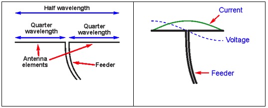
Figures 1a and b – Current Profile on a Half Wave Dipole Antenna

Figure 1a reminds us of the basic dipole geometry; and Fig. 1b shows the current and voltage profiles along the driven element.  (From http://www.radio-electronics.com/info/antennas/dipole/half-wave-dipole.php)

Note from Fig. 1b that the current profile of a dipole has a maximum current level at the center feedpoint and decreases to zero current at the end of each element arm.  Contrasting, the voltage profile has a zero value at the feed point and increases to a maximum level at the ends of the element arms.

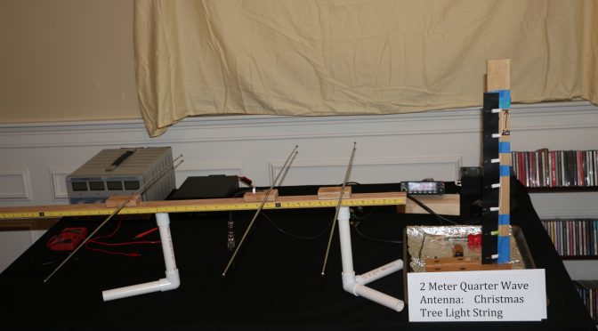
1/4 Wave Vertical. Note the 7 spaced lamps.
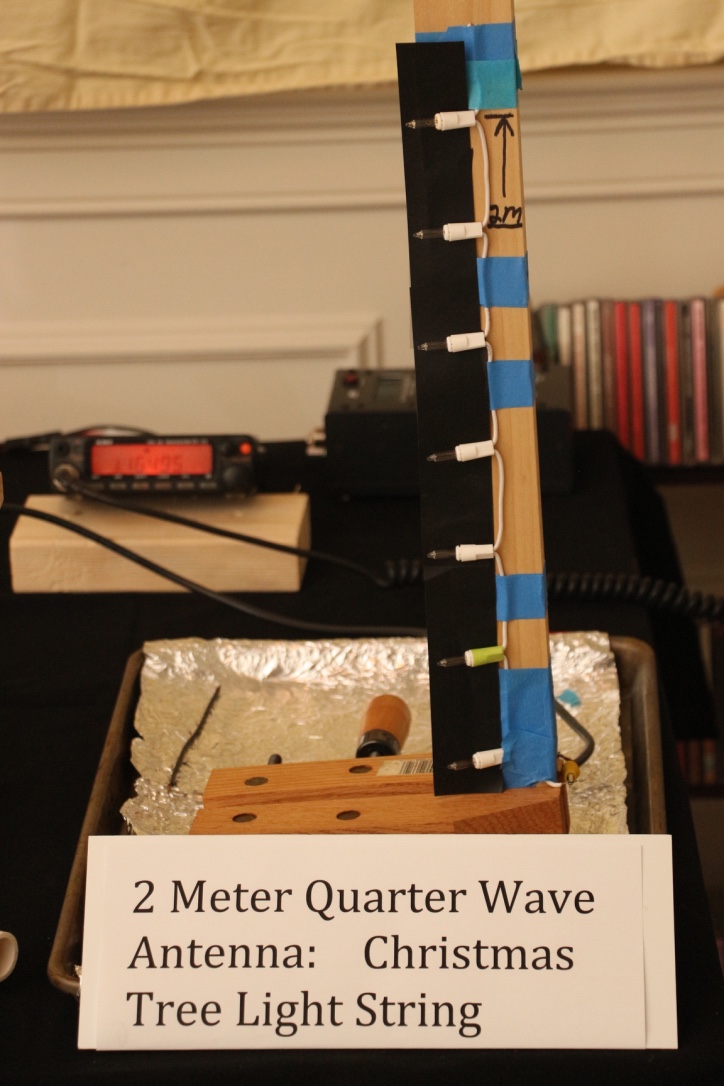
Figure 2 – 1/4 Wave Vertical. Note the 7 spaced lamps.

The 1/4 wave vertical antenna seen in Figure 2 can be used to visualize the current profile along the arms of a 1/2 wave dipole.  The 1/4 wave antenna is made from a short length of a Christmas tree (incandescent) light string.  The string length can be estimated from the standard equation:  Length (ft) = 234/Frequency in MHz. Generally, several inches needs to be trimmed off because the lamps add “electrical length”. The shown antenna has the same resonance frequency as the Lego Style dipole we will use later (i.e., 146.550 MHz). The top end of the antenna is marked by the blue tape immediately above the 7th lamp.

Transmitting mode. Note pattern of lit and unlit lamps.
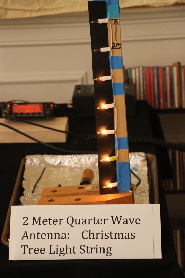
Figure 3 – Transmitting mode. Note pattern of lit and unlit lamps.

The energized antenna with 15 watts RF signal is seen in Figure 3.  Compare the pattern of lit and unlit lamps with the current profile sketch shown in Fig. 2b.  The three lamps, counting from the picture bottom are brightly lit from an RF current.  Lamps 4 and 5 show progressed less light indicating a lower RF current.  Lamp number 6 is barely lit and number 7 is dark indicating together very little to no RF current at the element top end.  The light pattern is a clear mimic of the diagram in Figure 1b.

Demonstration of the Voltage and RF Radiation Profile on a Half Wave Dipole Antenna

The voltage profile on a center fed 1/2  wavelength dipole is seen in Figure 1b. As mentioned above, the voltage is zero at the dipole center and increases in monotonic fashion to a maximum value at the antenna ends.

Illustration of Dipole RF Radiation Pattern
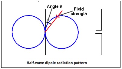
Figure 4 – Illustration of Dipole RF Radiation Pattern

The familiar RF radiation pattern of a dipole is shown in Figure 4 (taken from the cited source for Figure 1).

We are all well-schooled on the pattern, so I will just list the three key facts.  First, the RF radiation is broadside to the antenna axis. Second, the RF field intensity is equal on the left and right sides of the dipole axis (i.e., there is no discerned “front to back” sidedness. Third, there is (theoretically) no RF radiation off the ends of the dipole wire.

The dipole voltage profile and the RF radiation pattern can be demonstrated using the basic dipole element of our “Lego Style” antenna and two simple tools. The voltage profile, or more correctly, the electric field strength around the dipole is sensed by a small fluorescent light tube.  The actual RF radiation from the energized dipole is sensed by the flashlight lamp-bridged receiver antenna introduced last month in Part 1 of this series.

  1. Direct RF Radiation Visual Detection

The video below (double-click in the picture box) demonstrates the use of the lamp-bridged receiver antenna to detect radiated RF power.

The video shows the flashlight bulb bridging the handheld receiver antenna lights up when it detects an RF signal that matches its resonance point at 146.550 MHz  The light bulb is dark with no transmitted RF power from the Lego dipole. Keying the radio energizes the Lego dipole and the receiver lights up about equally on the right and left sides of the Lego antenna.  This reflects the figure 8 pattern of RF power illustrated in Figure 4.

  1. Voltage Profile witnessed by the Electric Field Strength.

The next video (double-click in the picture box) employs the fluorescent light bulb to map the voltage profile along a dipole arm by sensing its electric field strength.  An RF electric field causes a series of chemical reactions within the light bulb that produces a bright fluorescent light.

The light bulb is dark when the Lego dipole is not transmitting an RF signal. Keying the radio generates an RF signal and the associated electric field around the dipole element causes the bulb to light up. Note, the bulb is very bright adjacent with the side end of the dipole arm and extinguishes as it is moved to the dipole centered feedpoint. Also, the light is dimmed at the antenna tip in-line with the dipole axis.

The voltage profile map seen in the fluorescent light bulb video augments the RF signal map seen in the lamp-bridged receiver antenna video.  Also, it extends our demonstration to the expected observation that there is (theoretically) no RF radiation off the end tips of dipole elements.

CONCLUSION 

In this second installment of our Lego-Style Antenna series, we have shown how this construct together with two simple tools can be used in the classroom to demonstrate basic properties of the ubiquitous dipole antenna; Namely, criterion of resonance, generation of RF radiated waves, the polarization of the RF field (horizontal or vertical) and the general propagation geometry of these waves relative to the antenna orientation.

In Part 3 and last installment of this series we will continue to use the Lego-Style Antenna in its’ Yagi configuration together with the two accessory tools to show how properly designed and placed reflector and director elements on the Yagi antenna can shape and control the dipole rf signal to increase gain via spatial directivity  and improve signal selectivity by the “front-to-back” ratio that it creates.

73 & Hope to hear you on the air,

Dave N1RF

Moxons in the Attic (Part 1)

A few months ago, I wrote an article on building a stealth antenna farm. Since I live in the land of CC&Rs, antennas must be “dual use” such as a vertical hidden inside a PVC flagpole, or low dipoles and inverted Vees hidden in trees. I spent many years as an avid contester and DX-chaser to appreciate the logic of stacked beams on towers to enhance the thrill of the hunt. Thanks to Layne, AE1N, I checked out the website of Jeff, AC0C (www.acoc.com) for some ideas of how to build a multi-band station in one’s attic without the condo association vigilantes running him out of town. Jeff spent countless hours crawling around his attic to construct multi-element antennas for 160 through 6 meters. Spurred on by Jeff’s success, I decided to explore the attic of my garage to see what I could do. As I described in the MAY Nashua ARC bulletin, I settled on building Moxon antennas for 15 and 17 meters.

An old adage about antenna building states that an antenna must be built-in lousy weather in order to work right. Thirty years in New Hampshire lent credence to this axiom as I spent many a cold, windy day on a tower doing antenna work. In Florida, a similar law applies: build an antenna in the summer months while sweating profusely rather than during the comfortable winter weather. Again this makes sense: DX and contesting fill up the winter months to have time to mess with antennas. It is also important to remember that, during such endeavors, you will become enamored with you antenna as you take breaks to warm your body (in NH) or drink a gallon of water (in FL), all the while cursing this law of antenna building.

But I’m getting ahead of myself. My garage attic is roughly 20 x 20 feet with an apex of about five feet that runs north-south. I had selected the Moxon design because a conventional 2-element beam would not fit in the space available. I elected to build a Moxon for 15 and 17 meters that would fit in the space available without having to encounter obstacles like the ventilation duct work. I was also fortunate in that my home is one of the older models that do not have foil-backed insulation inside the roof that creates a radiation-proof box. The joists junctions are reinforced with metal plates as part of hurricane building codes. My plan was to attach the wires to the roof trusses and stay away from these plates as much as possible to avoid interaction.

The 17-meter Moxon is a little over seven feet between elements while the 15-meter Moxon is about six feet between elements. I used a piece of half-inch PVC pipe as a template to mark the joists for the 17-meter antenna. The antenna is about 2.5 feet above the attic floor for a total height of eleven feet above the ground. I had modeled it at 13 feet so I figured it would be close enough. The 15-meter Moxon is about 15 inches above the 17-meter one. When viewed from the top, the antennas look like concentric rectangular loops.

Over the course of several weeks, I grunted, groaned and sweated my way back and forth measuring and installing the wires. I worked during the morning hours before I was soaked before 10:00 AM. I found myself wishing I could have my five-year-old grandson help me. He can stand upright and is plenty flexible to maneuver around the joists. While I did not have to worry about the obvious safety issue of working on a tower, I did at times feel I was a candidate for the NFL concussion protocol from bumping my head. I tried using my cycling helmet but it interfered with my headlamp. Another similarity to tower work is that I had to make N trips back and forth in the attic for stuff I forgot. This is, however, much more bearable that climbing up and down a tower to get what I forgot.

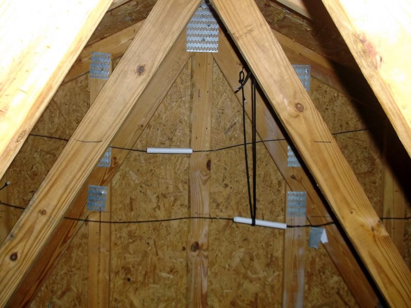
Figure 1 shows a view toward the south end of the attic. The two pieces of PVC form the element separators for the 15-meter Moxon (top wire) and the 17-meter Moxon (bottom wire).

Figure 1 – Moxon Element Separators, 15m (top) & 17m (bottom)

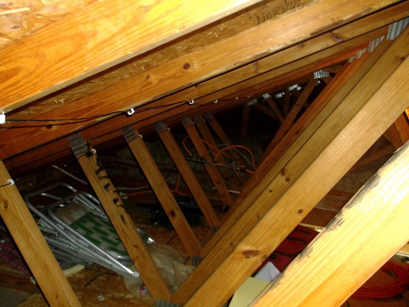
Figure 2 shows the reflector elements for each antenna as secured to the joists, looking north through the attic. The white standoff fasteners are coax cable tie-downs that I found at the hardware store. Standard house wiring fasteners would have worked but they leave little room for pulling wires if I needed to make adjustments. (My first attempt was to use duct tape to hold the elements up. However, the heat soon made them droop.)

Figure 2 – Moxon Reflector Elements, 15 m (top) & 17m (bottom)

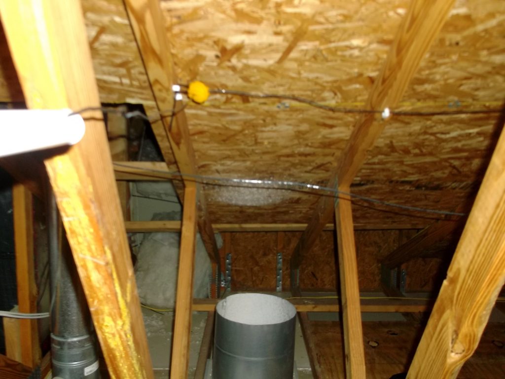
Figure 3 shows one corner of the director of each antenna looking east. The duct work to the left is part of the ventilation system while the open duct vents directly from the garage below. The yellow fence standoff on the upper antenna is the bend point for one end of the 15-meter director. Not visible to the left is a similar bend point for the 17-meter director.

Stealth Antenna - Looking East-from the Reflectors
Figure 3 – Looking East-from the Reflectors

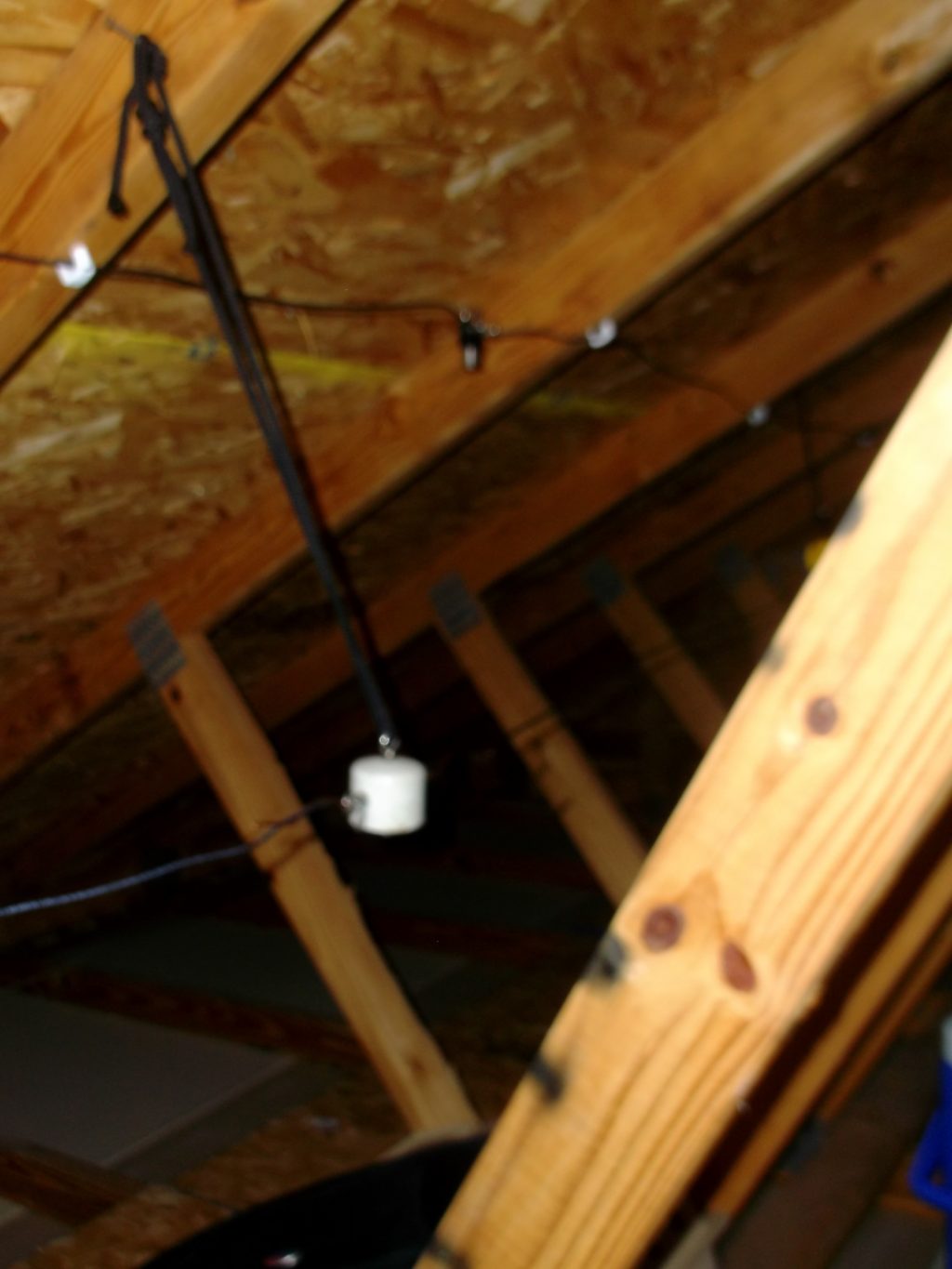
Figure 4 shows the temporary feed points for each antenna.

Stealth Antenna – Feedpoint for 15m (top) & 17m (bottom)
Figure 4 – Feedpoint for 15m (top) & 17m (bottom)

The figures above show the project to date. I installed the 17-meter antenna first and measured its SWR performance with my analyzer. I found that it resonated beautifully at 16.7 MHz with a 1.1:1 SWR while bulging to 3.9:1 at 18.1 MHz. I shortened each element by a foot and ran measurements again, this time the resonant point moved up to 17.3 MHz (1.3:1 SWR) and the SWR at 18.1 MHz dropped to 2.7:1. I folded the elements back another four inches on each end and measured the response. I observed the SWR bottoming out at 1.5:1 at 18.1 MHz where I wanted to be. As a point of interest, I modeled a Moxon designed for 16.7 MHz and noticed the elements were about two feet longer than a Moxon designed for 18.1 MHz, close to the twenty inches I had to shorten the elements. Apparently, there is some interaction with the wiring that runs along the attic floor near the edges.

Armed with the satisfaction I was on the right track, I installed the 15-meter Moxon above the 17-meter antenna. I hooked up the analyzer and fired it up only to find to that its “resonant” point was a dismal 3.0:1 SWR at 22.9 MHz, rising to 3.9:1 at 21.1 MHz. This meant my antenna was too short. I went back to EZNEC, opened the standard dipole model and plugged in 22.9 MHz and found that its length was very close to the overall driven element for a Moxon designed for 21.1 MHz. I lengthened each element by five inches as a starting point to see what would happen. The result was no change in SWR at 22.9 MHz while dropping slightly to 3.6:1at 21.1 MHz. Hmm, looks like I need to get a little smarter about this.

Stay tuned for Part 2 to find out. (Don’t you hate that?)

Ed, K2TE

Radio Amateurs Developing Skills Worldwide