Having SDR capabilities like a waterfall display and point-and-click tuning can be added to your existing station. I’ll show you one easy way to do it.
Antenna port management
Care must be taken that your SDR is protected from your transmitted signal. If you are sharing an antenna between your rig and an SDR receiver you need to ensure that your transmitted signal doesn’t go directly into a receiver! Years ago hams had receivers and they had transmitters. They switched between the two as they worked. The receiver was isolated from the transmitter while transmitting. Your transceiver does the same thing. It uncouples the receiver from the antenna when you transmit.
Some radios allow you to tap into the receiver’s receive path. My ICOM IC-7600, for example, has two RCA connectors labeled “RX ANT IN” and “OUT.” The IN and OUT are normally connected together. That is the default and in this condition things work exactly as you expect. But, you can select an option that separates these two signal paths.
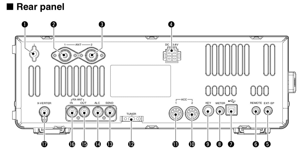
Figure 1. Refs 16 and 17 are RX ANT IN and OUT, respectively.
Figure 2 shows this relationship a little better.
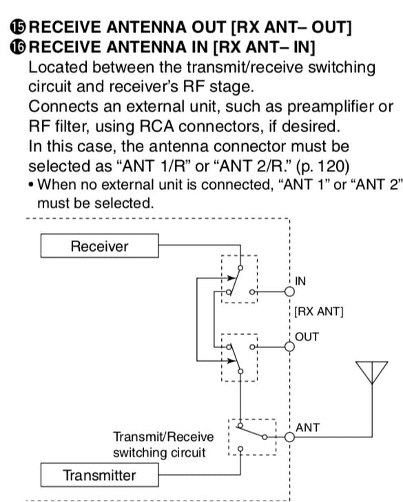
Figure 2. Receive signal management in an IC-7600
If you had a receive-only antenna (like a Beverage) then you would separate the path, isolating your receiver from the transmit antenna, and sending it instead to your receive-only antenna (Connected to IN.) That configuration shown in Figure 2 is the default where the receive and transmit antenna are the same. If the relays around IN and OUT were switched the other way, the connection from the receiver to the transmit antenna can never happen. That’s how we ensure our receive-only antenna is used during receive. (It would be connected to RX ANT IN.)
Splitting the signal
In this exercise we’re going to add an SDR to the mix, not a receive antenna, but we use all the same stuff. What we need to do is tap into the received signal for the SDR without disturbing (too much) the signal that goes into the receiver of the ICOM. That is, I want to take the one signal (from the antenna) and split it between two receivers (the ICOM and an SDR). There is a device that does that and I’ve pictured it in Figure 3.

Figure 3. A Mini-Circuits signal splitter.
This device is about as simple as something like this gets. The Mini-Circuit ZFSC-2-6+ takes one input and splits the signal to two outputs. So, we take the signal received from RX ANT OUT, send it to the splitter, and then take the two outputs and route one back to RX ANT IN (for the ICOM) and the other to an SDR. Now all you need to do is ensure your radio is using ANT 1/R or ANT 2/R so the signals remain split.
Choosing an SDR
There are many, many small SDR receivers available. I selected the SDRplay RSP 2 receiver as shown in Figure 4.
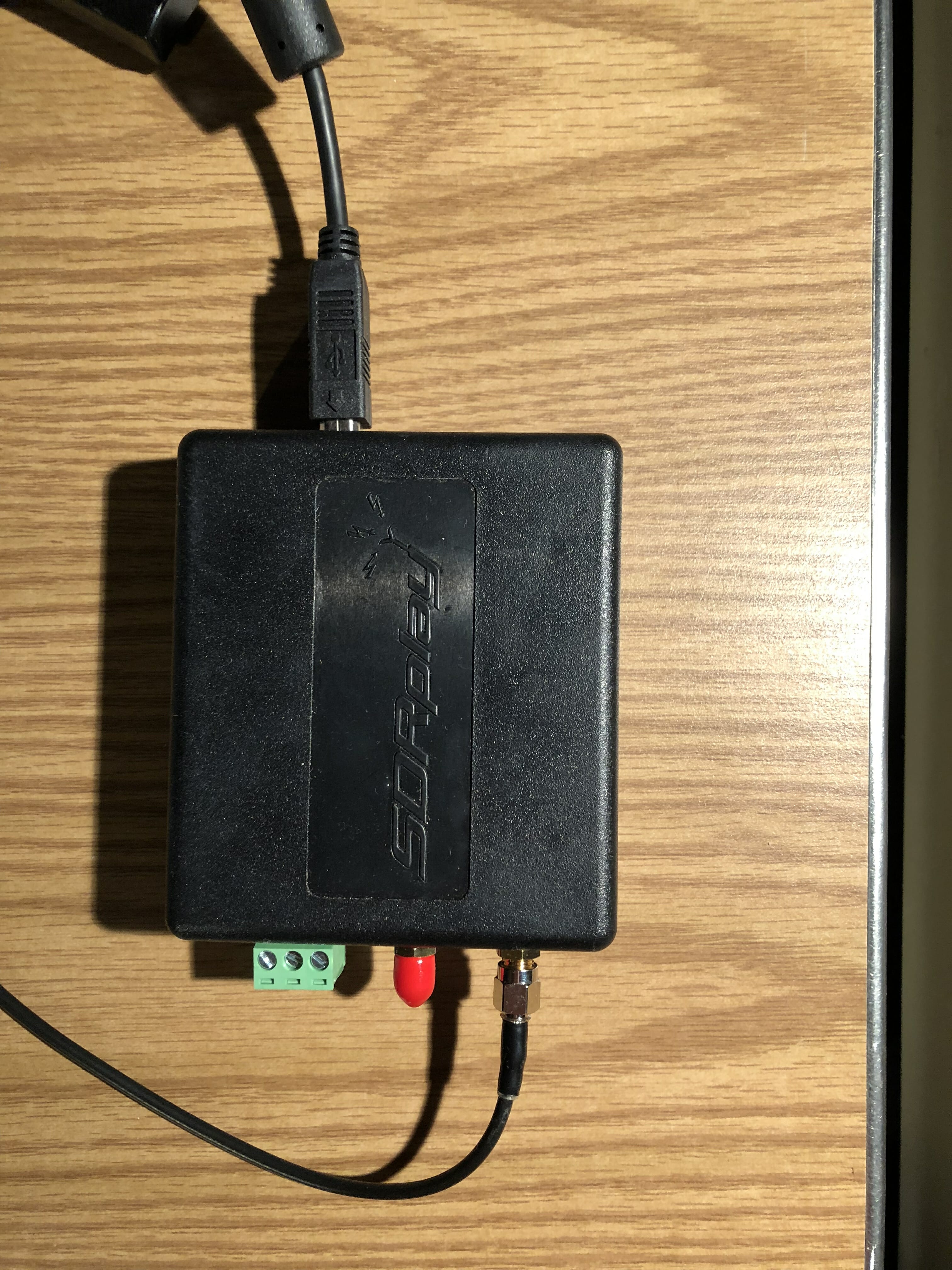
Figure 4. The SDRplay RSP2 receiver
The antenna connection comes from one of the ports of the signal splitter. The unit is powered by, and communicates to, the computer via the USB cable shown near the top. This is a small unit and I tuck it neatly behind some other stuff and out of the way. There are no controls on the unit so there’s no reason to handle it again.
Software
Just as there are many choices for SDR receivers, there are many many choices for software. Ask any ten hams which one is best and you’ll likely get eleven answers. So, I recommend trying a few for your platform (I’m on a Mac) and see which one you like best.
SDRplay recommends CubicSDR and I’ve found the software fairly easy to use with an easy learning curve. SDRplay has software for the following platforms:
- Windows
- Linux x86
- Mac
- Raspberry Pi
- Android
- ARM64
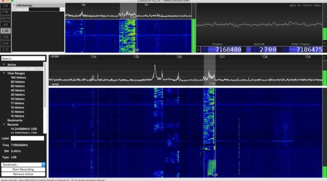
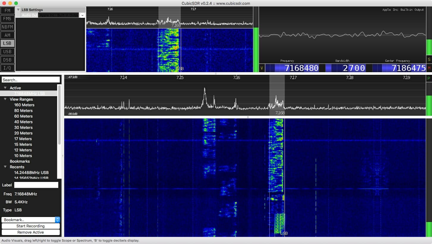
A screenshot of CubicSDR is shown at the top of this article.
The software allows me to see a wide slice of spectrum, a waterfall showing a history of signals, point-and-click tuning (once you’ve enabled rig control), and, of course, it is a receiver so it gives me sound from the tuned signal through my computer speakers.
Performance
The splitter has very little insertion loss (0.3 dB), but of course the signals themselves will each be down about 3 dB (since each signal is half the original). A loss of 3 dB is about half an S-unit, so you’ll never hear the difference. And, since the SDR is much more sensitive than my ears I consider its addition a win.
Impressions so far
I used this system while playing in the California QSO Party. It was fun clicking on a signal in the waterfall and having the radio obey my request. Hard-core SDR fans will likely talk about the power of visualization for finding a signal, or even finding open spots if you wish to call CQ. With this arrangement, you can have all that using your existing radio.
Coming in December
Would you like to try building an SDR for about $25 plus a Raspberry Pi? Come to the December Tech Night where we’ll have an SDR workshop. More detail on this to follow in a few weeks.
Links
- SDRplay.com
- airspy.com
- HackRF
- RTL-SDR
Scott, NE1RD