
Kit build for 2019
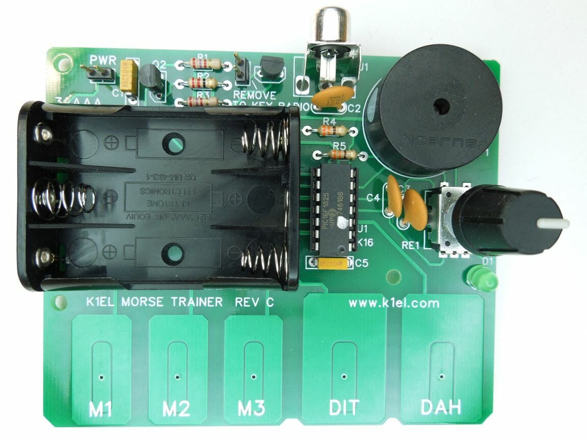
The change of seasons brings us again to the darkest months, a good time to concentrate on indoor activities like station updates and kit building. This February 12th the club will hold its annual kit build during Tech Night. The kit selected this year is the Morse Tutor Keyer Kit by K1EL. You can have a quick look at the manual for this kit here.
Club buy of kits
As part of its STEM initiative, NARS has purchased a number of these kits in bulk and has been using them in student kit builds in local area schools. Buying directly from the club means getting a discount on the kit, and directly supporting this educational outreach.
BUY THE KIT HERE: MTB-KIT order page
What to bring to kit build night
The kit will supply the board and parts necessary to complete the project. You’ll need to bring appropriate tools including:
- Soldering iron and solder
- Small needle-nose pliers
- Small diagonal/flush cutters for trimming component leads
- Small flat blade and Phillips head screwdrivers
- Your reading glasses (a note to myself, if no one else!)
- A printout of the manual for the kit (or a copy downloaded to your tablet)
- Recommended: Multimeter
- Optional: a small magnifying glass
Don’t forget to bring batteries! The unit requires 3 AAA cells.
The spirit of kit build night
NARS has many new members since the last kit build. Those of us who have experience with kit building should lend a hand to those new to the adventure. Take a moment and help mentor your fellow club members, especially our youngest recruits, so they walk away with a working kit and the sense of accomplishment that goes with it.
Remember: Watch for the link on the website for ordering your kit.
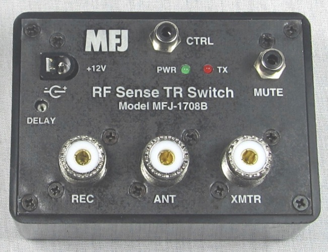
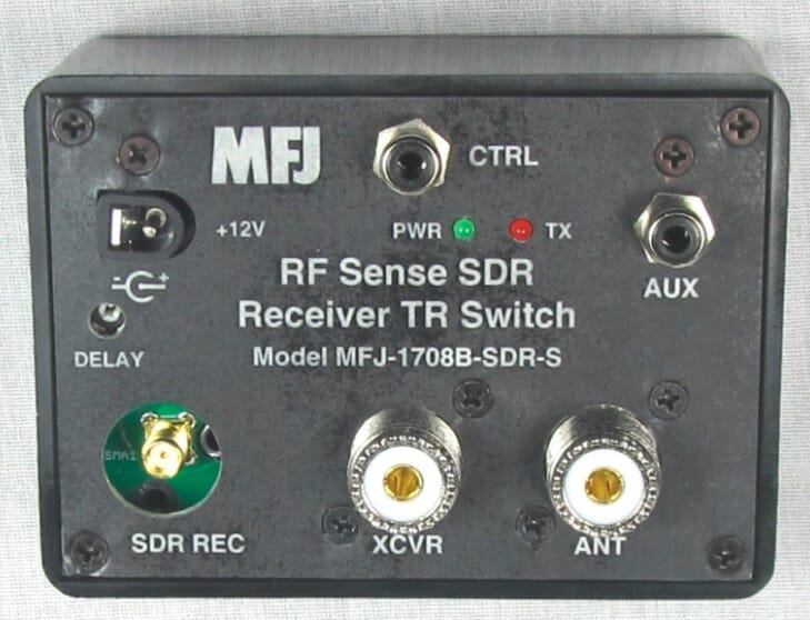
![Add SDR Capabilities to Your Radio [part 2]](https://www.n1fd.org/wp-content/uploads/2018/10/MFJ-1708B-651x372.jpg)