The Nashua Area Radio Club has a dedicated team of Ham Radio license class instructors and we offer Technician, General, and Amateur Extra classes twice a year. We have a great track record using the Gordon West class materials and have 68 graduates who got their initial license or upgrade.
Our classes are held at Dartmouth-Hitchcock Nashua, 2300 Southwood Drive in Nashua.
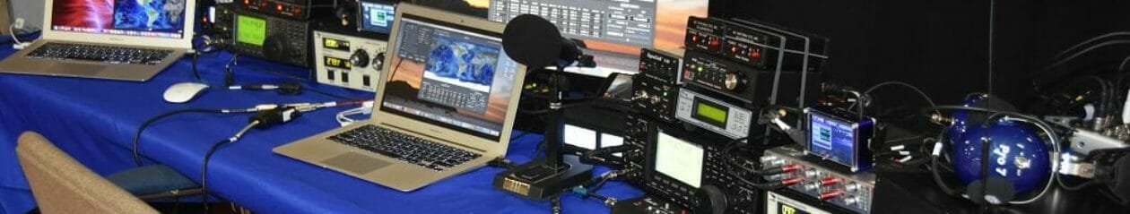
We setup a live VHF and HF station in the classroom, which allows us to provide live demonstrations of the class material. This helps students to better understand the material and also give them an idea of what they can do with their license once they have it.
Class Radio Station
This season, two new instructors have joined our team, Greg Fuller, W1TEN and Brian Smiglieski, AB1ZO, who are both graduates of our May 2016 Extra Class. They join our existing instructors Dave, N1RF, Skip K1NKR, Wayne AG1A, Aron W1AKI, Anthony, KC1DXL, Wayne, KB1HYL, Fred, AB1OC and Anita, AB1QB.
We will hold a License Exam Session at the end of each class, starting a 4:00 pm on Sunday.
We have scheduled 3 classes for this fall:
Date
Class
Class Fee (due in advance)
Book
September 24-25
Technician
$30
Gordon West Technician Class Manual 2014 - 2018
October 22-23
General
$30
Gordon West General Class Manual 2015 - 2019
December 2-4
Amateur Extra
$40
Gordon West Extra Class Manual 2016 - 2020
More information can be found in the flyers below. Please pass this information along to anyone you know who is interested in a Ham Radio License or an upgrade. Contact Anita, AB1QB at [email protected] to sign up.
We held our second series of National Parks On The Air Activations this past week. The weather was beautiful and we have the pleasure of activating two different parks this time.
We took turns operating as two person teams with an operator and a logger. The IC-7000 radio which we use in our Mobile HF station is easily accessible for connection and we brought a laptop running N1MM+ which we connected to the radio. This made logging accurate and easy. We made a little over 210 QSOs in about 2 1/2 hours in Marsh-Billings-Rockefeller on Saturday.
Saint-Gaudens NHS
On Sunday, we activated Saint-Gaudens National Historic Site (NPOTA NS60) for the second time. In addition to the gang from Saturday, Joe KB1RLC and Jill Gordon, Jeff Millar WA1HCO, Ira Brand KC1EMJ and Mike Ryan K1WVO joined us for the Sunday activation.
Portable Antenna – 20m Inverted-V
We arrived early on Sunday and began our operation by setting up and tuning a 20m Inverted-V antenna for our portable station. We were able to get the feed point of this antenna up higher (about 35 feet) this time and the antenna performed better as a result.
Portable Operation With A View – NPOTA NS60
We setup our 20m portable station in a shady spot at the bottom of the park’s meadow. This gave us a nice view while operating.
20m Portable Station
We used our 20m portable setup which is based upon the 100w Icom IC-7300 again for our second activation and it worked very well. We had a laptop computer running N1MM+ for logging.
Nashua Area Radio Club Operating Portable In NPOTA NS60
The 20m portable station tent was our main “hang out” during our NPOTA activation on Sunday.
Mobile HF On 40m In NPOTA NS60
We also had our Mobile HF station at Saint-Gaudens and we operated it on 40m. We were QRO at 500w from the Mobile.
40m Bandpass Filter – 500W
We used the new bandpass filters from DXEngineering on both the 40m Mobile HF and 20m Portable stations. These filters have very low passband loss and very good filtering characteristics. We had no problems with interference between our 20m and 40m stations during our activations.
Saint-Gaudens Park Staff
The park staff rolled out the red carpet for us during both of our NPOTA activations. They displayed our signage and shared the information that we provided about the NPOTA program and our club. They really made us feel at home in the park.
Great Weather And Music Draws A Crowd
There was a large crowd of visitors at the park during our activation. The combination of great weather and live music was a huge draw for folks. This gave our club and our NPOTA activation some nice public exposure.
Abe Lincoln Sculpture
Saint-Gaudens was a renowned culture in his time and there are many impressive pieces of sculpture on the park grounds. The park recently commissioned this impressive sculpture of Abraham Lincoln which has become one of their centerpiece works in the park.
Flower Gardens At Saint-Gaudens
The park has many beautiful gardens and they offer a wonderful set of surroundings for the sculptures in the park.
Our Favorite Walkway In The Park
This is my personal favorite spot in the park – a Birch tree-lined walkway!
Team Operating Our Portable Station
Our NPOTA operations kept us pretty busy all afternoon on Sunday. We operated as two person teams – an operator and a logger. This gave more of us a chance to operate and the teamwork made it easier to handle the steady stream of callers.
More Team Operating
I got a chance to operate both the mobile and portable stations. It was great fun handling our contacts with NS60!
Eyeball QSO With A Local HAM
It seems that every Amateur Radio operation that I have the pleasure to be part of manages to hand our a nice surprise or two. This one was not an exception. I worked a local HAM, Jeff Katchen WB2NWR, in Cornish, NH which is very near the park. He came by afterward to visit and share his QSL card and a nice eyeball QSO!
Our operation was a lot of fun – a success by all measures. We made a total of 570+ QSOs between our activations on Friday and Saturday.
There was some discussion at the end of the day on Sunday about doing one more NPOTA activation this year. Our final one would be a high-power operation with both stations running QRO 500w! We will discuss this at an upcoming club meeting and we’ll certainly do a third activation if there are enough interest and support.
We took a lot of nice pictures between this last and our previous activations. You can look at them in the gallery which follows.
On July 10, N1FD members gathered in Cornish, NH to activate the Saint-Gaudens National Historical Site as part of the ARRL’s year-long National Parks On The Air (NPOTA) event which is celebrating the 100th anniversary of the National Park Service. We almost canceled it due to a prediction of thunderstorms, but the weather changed to merely intermittent showers, which we didn’t let get in our way.
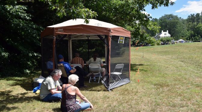
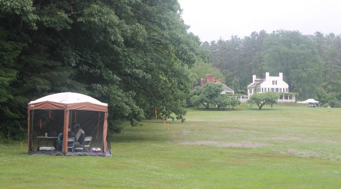
NPOTA Portable Station at Saint-Gaudens NHS
While the rain was still very light, the advance crew was able to set up the canopy that was last used as the food tent during our recent Field Day operation. It was more than adequate to keep the 100W station and a handful of club members dry throughout the day. The site was on the edge of the meadow (a/k/a the reserve parking area) near the entrance to the Ravine Trail which was furthest from the buildings.
20m Inverted V Antenna
With the next carload of club members and a pneumatic launcher, we were able to put a line over the branch of a tree along the edge of the meadow and use it to hoist up a 20m dipole in an inverted “V” configuration. It only had to be lowered and raised a couple of times to tune it, and we got it right on the mark using an antenna analyzer.
20m Portable Station
A small, quiet generator was also set up on the edge of the field to provide power. This 20m antenna and generator were used on the 100W station, an IC-7300.
Mobile HF Station on 40m
A second station, Fred AB1OC’s 500W mobile station, was parked midway across the field towards the road and operated on 40m. I don’t know how many NPOTA activations have had multiple stations running at once, but a number of hams worked us on both bands.
One of Many Sculptures on the Park Grounds
Unlike our visits earlier in the year, park operations were in full swing for the season. All of the buildings were open to visitors. The park’s Resident Artist for this summer was working on a clay original to later be cast in bronze, and he paused to talk to us about his work. Club members were able to explore other modern sculpture, and also the sculpture by Augustus Saint-Gaudens, that is on exhibit throughout the grounds. A number of members walked the Ravine Trail, which descended into a deep ravine (what did you expect?) to a stream and a swimming hole used by Augustus Saint-Gaudens and his family and others who worked at the studios. People were also able to enjoy a bit of the Sunday afternoon concert.
Saint-Gaudens NHS Resident
Not too far from where our 20-meter station was, Mike K1WVO spotted a tiny salamander, a Red Eft, crawling across the forest floor. I’m not sure, but I suspect that a few Pokémon were also spotted in the park!
We also had some special visitors: a ham from California whose daughter worked at the Marsh-Billings-Rockefeller National Historical Park across the river in Vermont, and a local ham who worked us and then drove over for an eyeball QSO.
N1FD On The Air at Saint-Gaudens NHS
The rain continued off and on throughout the day, but it was never heavy — certainly not heavy enough to dampen the spirits of the Nashua ARC members who were too busy making or helping to log QSOs to notice it. The group logged a total of 528 QSOs in a little over 4 hours! At the end of the day, the equipment was quickly broken down and packed up, just in time for the rain to completely stop and the skies to clear for a pleasant drive home.
We’re hoping that you and your family can join us for the next activation of this park on August 7!