Ever since we built our Mobile HF Station, we’ve talked about taking it to Acadia National Park in Maine and operating from the top of Cadillac Mountain. The 2016 ARRL NPOTA event gave us the motivation to plan the trip for the week before Labor Day. The week before our trip, we saw an article in the ARRL Letter encouraging operation from the newly declared National Monument, Katahdin Woods and Waters in Maine, which had just be designated as NPOTA MN84. Visiting the NPS website, we learned that the park is only a 2 1/2 hour drive from Bar Harbor, where we are staying. We decided to accept the challenge to be the first to activate the new park.
Our F150 Mobile Station at the entrance to Katahdin Woods and Waters National Monument
Tuesday, August 30 was our first full day of vacation, we left our hotel room and parked by the Acadia visitor center and called “CQ National Parks”. We ended up with 76 contacts in the log from NP01.
After that we got on the road and headed toward Katahdin Woods and Waters, activating counties along the way including the county line between Penobscot and Aroostook Counties.
NPS Map of the Park
As a newly designated National Monument, Katahdin Woods and Waters does not yet have a visitors center or any signs showing you when you enter and exit the park. We just had the map (above) to determine where the park boundaries were. All of the roads in black on the map are gravel roads that are also used for logging trucks.
Entrance to Katahdin Woods and Waters National Monument
We entered the park from Swift Brook Road off Rt 11 in the lower right corner of the map. We drove through the lower section by the entrance and then headed north along the Eastern Branch of the Penobscot River and operated near the Loos camping area. The sign above confirmed that we were within the park boundaries.
Scenic View of Katahdin Woods and Waters NM
The scenery along the river was beautiful with views of the mountains in the distance.
Operating at MN84
We started operating on 20m and the pileups were huge! Everyone was excited to get this new NPOTA into the log. Fred, AB1OC/M ended up going split on 20m due to the size of the pile-ups. After a while, he moved to 40m to give the close in folks a chance at MN84. We went back and further between 20m and 40m until the pile-ups thinned out. We also made 18 QSOs with the club callsign N1FD to also give the club credit for the activation. We really enjoyed activating the park and the people we talked to were great! We made a total of 350 QSOs from MN84.
Activating MN84 for the first time was truly a memorable experience. We enjoyed it so much we will be back on Saturday to give more NPOTA chasers a chance at MN84! Hope to talk to you on the air!
This article discusses some work on designing a matching network to make antennas match well (low VSWR) across the entire ham band. This will be a described in more detail at the September Tech Night.
Antennas have an impedance (or match) that varies with frequency. Transmitters want to see a matched antenna with an impedance of 50 ohms. The antenna has the best match at one frequency and the match gets worse as the operating frequency changes.
Some bands and antennas are more challenging to match than others. Shortened or loaded antennas have a narrow range of match frequencies. The 75/80 meter band has a wide bandwidth in term of percentage.
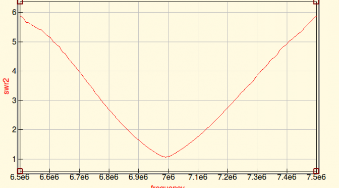
Here’s a plot of the SWR for my 40 Meter Dipole. It’s a good match at 7.000 MHz and degrades to about 2:1 at 7.100 MHz. Obviously, this is not optimized.
SWR for 40M Dipole
Modern radios have built in automatically adaptive matching networks make the radios work over a wider bandwidth, but networks are lossy and reduce transmitted power.
A manual antenna tuner has a lot lower loss than the built in tuner, but it requires manual adjustment. In fact, the extra tuned circuits generally act to make the antenna have even less bandwidth.
The QUCS RF circuit simulation program has the ability to model SWR, bandwidth, matching networks based on data about antenna performance. The antenna data can come from either an antenna modeling program such as 4NEC2 or EZNEC. Or the data can come from a measurement made by a good antenna analyzer.
QUCS also has a built in optimizer. It has the ability to try hundreds of circuit values and home in on an optimal design.
The optimizer setup needs a definition of “optimal”. For the case of a broadband antenna, “The worst case SWR anywhere in the ham band shall be as low as possible”. In the terms that QUCS understands, “minimize the maximum SWR over the frequency range 7.00 to 7.35 MHz.
Here is the result from running the optimizer on the data for my mistuned 40M dipole. QUCS has designed a broadband matching network that can achieve less than 1.5:1 SWR over the whole band.
QUCS achieved this by varying the components of a filter network. I drew a general filter network and let QUCS tune the component values. This network is designed with coaxial stubs.
The model of the antenna is stored as a file in the X1 file component. Line7 is a 30-meter coax feedline. The actual matching network consists of Line 1, 2, 3, 4. Each line is 50 Ohm coax. Line 1 and 3 are configured as open stubs. The line lengths predicted by the model are…
Line 1: 7.75 meters
LIne 2: 4.47 meters
Line 3: 8.49 meters
Line 5: 8.03 meters
Here’s another example. 160-meter antennas are often implemented as shortened loaded verticals. The loading makes the match very narrow-band. The red curve in the plot below shows a top loaded 160 meter vertical. It only covers a fraction of the band.
The blue curve shows the result of an optimization run that selected the values for a 7 component matching network. It achieves about 1.7:1 across the whole band. This network uses capacitors and inductors because coax stubs would be very long on 160 meters.
The component values for this network…
C1: 3450 pF
L1: 3.954 uH
C2: 3978 pF
L2: 6.951 uH
C3: 6156 pF
L3: 2.831 uH
C4: 4778 pF
I have not built any of these networks to see how they work in practice. The 160-meter network has some extreme values and it is probably very touchy to get right. Building that network to handle Tx power will require vacuum variable capacitors in parallel with high quality stable fixed value capacitors. But, the 160 network doesn’t really need 7 components. Put in one less stage of L-C and the ripple across the passband goes up a bit.
Conclusions
QUCS is a great RF circuit simulator. This shows that it can work with data from an antenna model or analyzer and can optimize matching networks to create a broadband antenna.
Summer is the time of year that many of us work on our antennas and improve our stations. Anita AB1QB and I did both of these things at our QTH this summer.
Removing Lower SteppIR Yagi From Tower
Our SteppIR DB36 Yagis were due for some maintenance so we took them off our tower. Special thanks to all the members of the Nashua Area Radio Club who helped us remove, recondition and reinstall our antennas! Matt Strelow, KC1XX of XX Towers and Andrew Toth provided equipment and know how to safely remove our two large SteppIR DB36 Yagis with help from the rest of us.
Lowering Antenna With Electric Winch
The SteppIR DB36 Yagis weigh almost 200 lbs each and Matt made good use of his electric winch to lower them.
Antenna Coming Down The Tram Line
The picture above shows the lower antenna coming off the tower. We used a Tram Line system to lower both antennas to the ground so that we could rebuild them.
SteppIR DB36 Antenna On The Ground
The SteppIR DB36 Yagis are quite large. They have 36 ft booms and the driven elements are almost 50 ft from tip to tip! They completely fill up our back yard when they are both off of the tower.
SteppIR Rebuild
Element Pole Sun Damage
The rebuild process began with a careful inspection of both antennas. They were both in good overall condition with some sun damage to the paint on the fiberglass element poles.
Disassembled SteppIR DB36
We removed all the element tubes and sweeps from both antennas for rebuilding. The picture above shows the disassembled upper antenna.
Rebuilt Stepper Motors Installed
All four Stepper motors on both antennas were replaced. These motors move metal tapes inside hollow element tubes to adjust the length of each antenna’s 4 movable elements. These adjustments are done automatically by controllers in our shack which receive frequency information from the radios which are connected to each antenna.
Reconditioned Element Sweep Poles
All of the element housing poles were cleaned, prepped and painted with a UV resistant clear coat to protect them from further sun damage. The poles cleaned up like new.
New Element Sweeps Ready For Installation
The assembly of all the new element sweep tubes (shown above) was done next. Each antenna has six sweeps.
Element Pole Preparation
The end of each element pole must be prepped with a tape system which ensures that the poles are seated properly, sealed to and firmly attached to the sweeps. This process and the associated assembly and tightening of the element couplers was the most time-consuming step in the rebuilding process as it had to be repeated a total of 24 times.
Rebuilt Element Assembly
Here’s a picture of one of the rebuilt element tube assemblies. The ropes support the element tubes and keep them aligned when the antenna is up in the air. These elements are attached to the antenna motors with couplers and clamps.
SteppIR DB36 Yagi Rebuild Complete
The picture above shows the lower antenna with all the element tubes reattached. There is quite a bit of additional prep work associated with adjusting all the supports and taping all the exposed areas of the antennas which are susceptible to sun damage. Also, all the electrical wiring on the antenna must be checked to ensure good electrical connections and good overall condition of the wiring.
SteppIR Ground Testing
Ground Test Setup
The final step in rebuilding the antennas is to test their operation on the ground. This ground test is done to ensure that all the motors are working correctly and that the element tapes move smoothly inside the rebuilt element tubes.
Ground Test Results
Another important part of the antenna Ground Test is to confirm that the antennas have a consistent resonant frequency and SWR on all bands. The resonant frequencies and SWR levels are far from those that would be measured when the antennas are on the tower at operating height. The idea here is to confirm that a resonance exists and that its frequency and SWR readings are repeatable as the antenna is adjusted to different bands.
SteppIR Installation and Final Testing
Tramming Antennas Onto A 100 Ft Tower
With both antennas rebuilt, its was time for Matt and Andrew to return and, with help from folks from our club, reinstall the rebuilt antennas on our tower. The video above shows this process. It is quite something to see! The installation took about 3 1/2 hours.
Updated SteppIR Controllers
The last step in the SteppIR DB36 rebuild process was to install the latest firmware in the associated SDA100 Antenna Controllers. There were some integration issues between the updated SteppIR Firmware and our microHAM system but we are getting those worked out with help from the folks at both SteppIR and microHAM.
Transceiver Upgrade
Icom IC-7851 With Display Monitor
I recently had a major birthday milestone and Anita surprised me with a new radio – an Icom IC-7851. This radio is an upgrade/replacement for our Icom IC-7800. While the two radios are quite similar in their operation and interfaces, I did not want to install the IC-7851 until the SteppIR antennas were reinstalled and all of their upgrades were working properly with our current radios. With the antennas done, it was the time to install the new radio!
Icom C-7851 Transceiver
The Icom IC-7851 has several important performance upgrades. The most impactful one is a new low phase noise oscillator which significantly improves RMDR performance compared to the IC-7800. The IC-7851 is in the top-tier of Transceivers in Sherwood Engineering’s tests. The receivers in the IC-7851 are very quiet, have excellent Dynamic Range and perform great in when close-in interference is present.
Icom IC-7851 Display Monitor
The Icom IC-7851 has a higher resolution and faster display. It also supports higher resolution external monitors so we installed an upgraded display monitor along with the new radio. The IC-7851 has a number of new networking features and supports stand-alone remote operation over a LAN and the Internet. We are planning to use these capabilities to add a second remote operating gateway to our station. More on this in a future article.
The combination of the rebuilt antennas and the new IC-7851 Transceiver has our station performing better than ever. The antennas are working as well or better than when they were new and the IC-7851 has significantly better receive performance compared to its predecessor and is a pleasure to use.
We will be hosting the ARRL Rookie Roundup RTTY contest for our club members who have received their first license in the last 3 years next weekend and we’re going to use the new radio and rebuilt antennas for the contest.
This project was completed in a little over two weeks and was a lot of work. I could not have done the project without the help of the many folks in our club. Again, a big Thank You to all the folks in our club who helped me with this project! I hope that many of you will be able to find some time to operate from our upgraded station.
We use cookies to ensure that we give you the best experience on our website. If you continue to use this site we will assume that you are happy with it.