Tag Archives: HF

KC1XX Contest Station Visit

The Nashua Area Radio Society recently had the opportunity to visit Matt Strelow, KC1XX’s station in Mason, NH. Matt has assembled one of the top contest stations in the world along with a very skilled set of operators.

Matt and some of his team members spent an afternoon with us helping us learn about how a world-class multi-multi contest station is built and operated.

KC1XX Antenna Farm

Bob WA1Z Explaining the KC1XX Antenna Farm

Our tour of the KC1XX Contest Station began with the antenna farm. Matt’s station is located on top of Hurricane Hill in Mason, NH, and sports some very impressive antenna hardware. Bob, WA1Z gave us a great overview of the impressive antenna hardware at Matt’s station. Matt has a total of 13 towers which include stacks of yagis on many of the HF bands.

KC1XX Contest Station
40m Tower at KC1XX

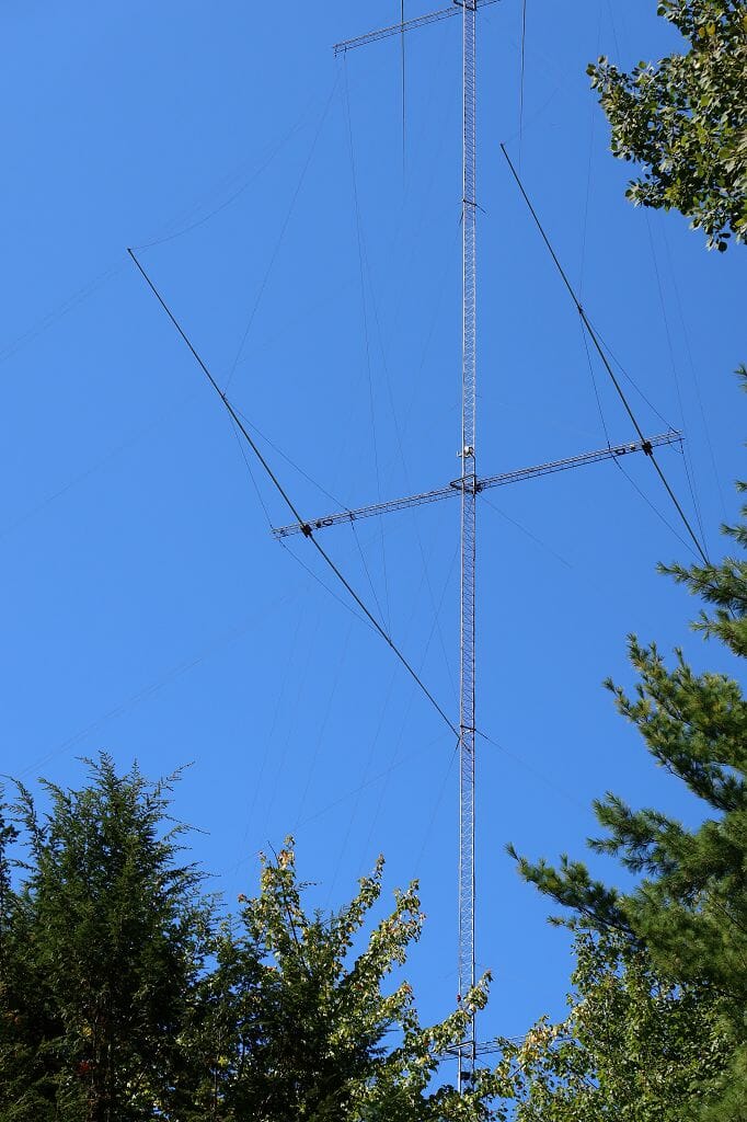
The photo above shows the 40m stack at KC1XX. This tower has two 40m, 4 element full-size yagis in a stack. The entire tower rotates at the base. As is the case with most of Matt’s towers, this one also includes antennas for other bands (in this case 6m and above).

Rotating Tower Base

It takes some heavy-duty hardware to rotate an entire tower. The photo above shows the rotator at the base of one of Matt’s rotatable towers. Rotatable towers are a great way to turn stacks of yagis which are fixed in the same direction on the same tower.

KC1XX Contest Station
2 Element 80 Antenna System on a 300 ft tower

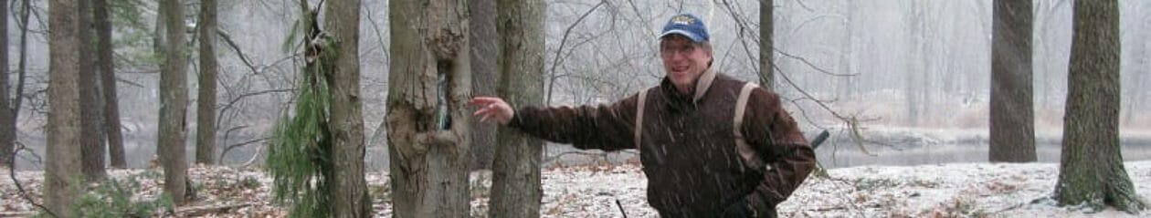
Matt’s largest tower holds a pair of 80m delta loops that create an 80m directional antenna. A two-element loop antenna is equivalent in performance to a 3 element yagi. This tower is 300 ft tall, is painted red and white and has a flashing beacon at the top! The “booms” that support the element for Matt’s 80m directional antenna are made from a pair of tower sections that are mounted horizontally on this tower.

Feedline Patch Panel

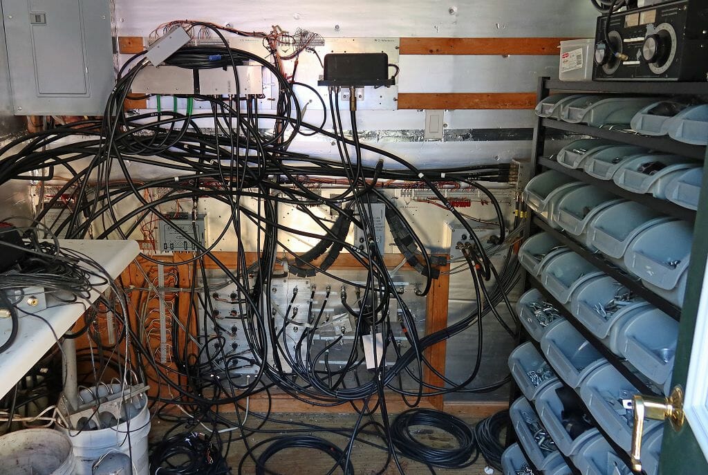
Matt’s station has many antennas and all of the associated feedlines converge in a small building that houses a patch panel, remote antenna switches and supporting gear.

KC1XX Station

KC1XX Contest Station
Operating Positions at KC1XX

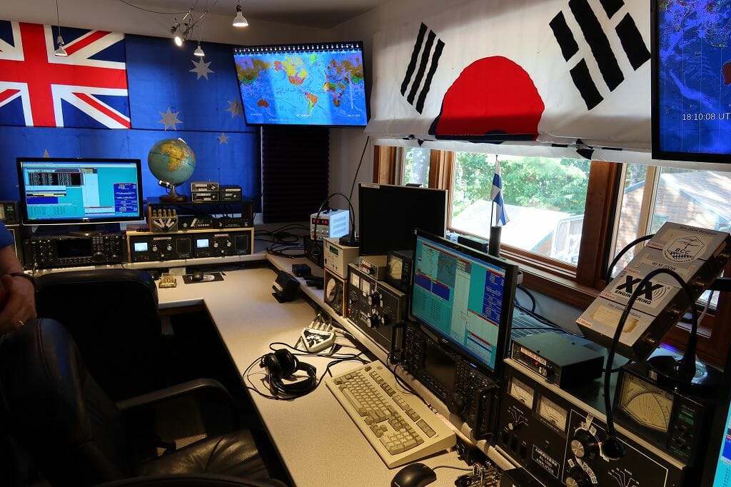
Matt’s “shack” is equally impressive. His station arranged in a multi-multi configuration with dedicated radios and operating positions for each band and major contest direction.

KC1XX Contest Station
Antenna Controls at KC1XX

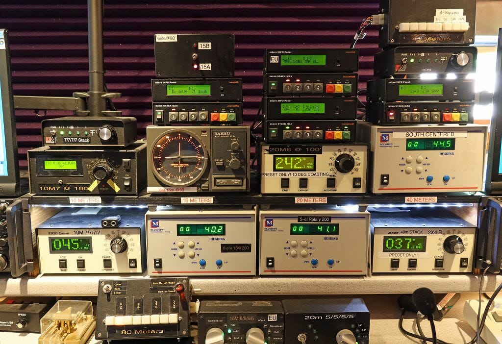
The antenna controls for the station are centrally located in Matt’s station. The antenna control system at KC1XX includes many antenna rotator boxes, antenna switches, and related controls. Centralized antenna controls allow all of the antennas to configured from one place in a way that best supports the band and contest conditions at any given time.

The Best Part of All

KC1XX Contest Station
Dave KM3T and Matt KC1XX Explain the KC1XX Station and Contesting

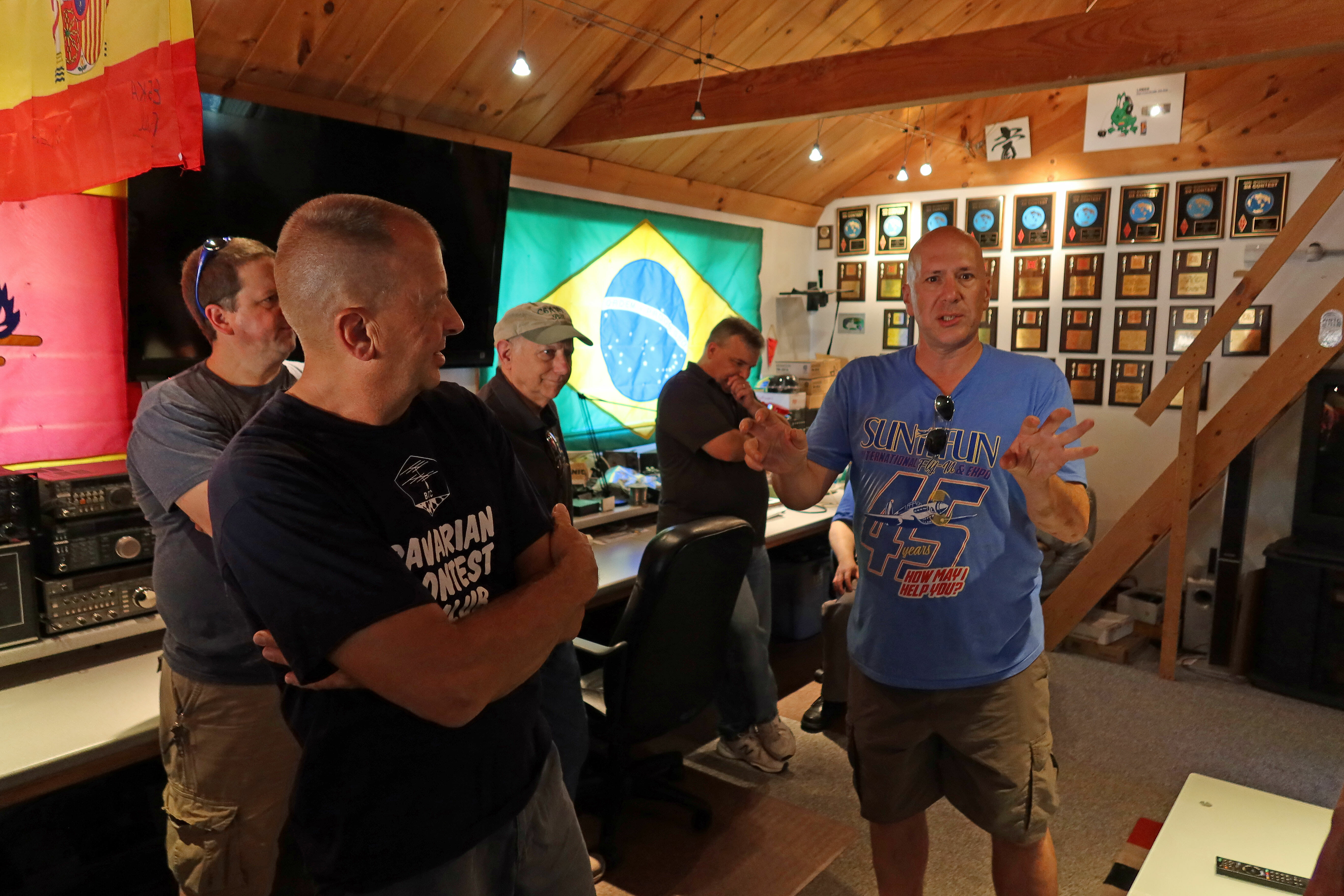
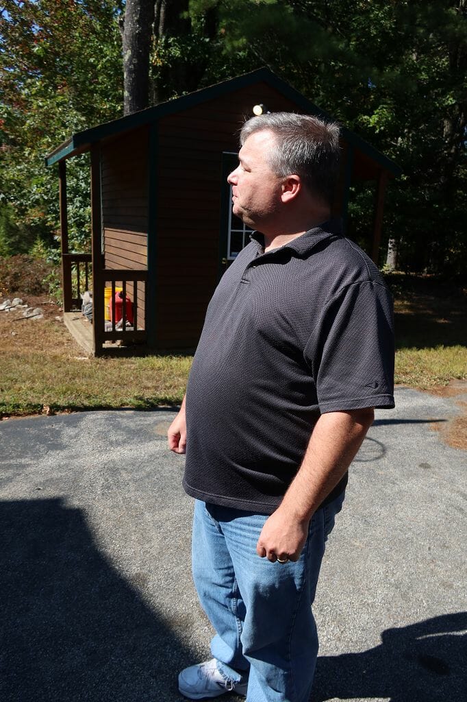
The best part of our visit was the time that Matt and his team spent with us talking about Amateur Radio and contesting. The photo above shows Dave, KM3T who is one of Matt’s team members explaining the station as everyone looks on. Dave is also a NARS member and it was great that he was able to join in our visit.

Matt created a really cool Amateur Radio quiz that we all did. It included questions involving recognizing call signs, propagation, and other areas of Amateur Radio operating.

We all really enjoyed the visit and we especially appreciate all of the time that Matt and his team spent getting to know us and sharing stories about everyone’s Amateur Radio experiences. We very much appreciate Matt’s and his team’s willingness to spend time with us sharing their knowledge and experience.

Fred, AB1OC

October Contest Notes

It Begins!

October marks the unofficial beginning of the radio contesting season. In the next few months, we’ll have CQ WW SSB, CQ WW CW, ARRL Sweepstakes CW, ARRL Sweepstakes SSB, ARRL 160m, ARRL 10m, and a whole bunch of little but fun contests like ARRL School Club Roundup. There are still QSO parties to chase on a random weekend, too, including CA, NV, AZ, PA, SD, NY and, IL.  If you’ve been having trouble making time to get on the air (as I have!) then there are a lot of excuses to put yourself in the saddle and make some Qs!

October Contest Highlights

CQ Worldwide SSB [0000Z, Oct 26 to 2359Z, Oct 27]

Exchange: RS + CQ Zone (5905 for New England)

This was the first contest I ever entered. It was 2002 and the bands were hopping. I had just hung a stealth antenna and was curious about what I could hear. It was amazing. The bands were full, all the other guy wanted was “5905”, and he was off to work the next one. No microphone jitters here—there wasn’t time! If you’re new to contesting give this a try. Do search-and-pounce (S&P), listen, listen, listen, then work them. By the end of the weekend, you might have DXCC!

California QSO Party [1600Z, Oct 5 to 2200Z, Oct 6]

Exchange: CA: Serial No. + County; non-CA: Serial No. + (state/VE area/DX)

Nevada QSO Party [0300Z, Oct 12 to 2100Z, Oct 13]

Exchange: NV: RS(T) + “NV” + county; non-NV: RS(T) + (state/province/”DX”)

Arizona QSO Party [1600Z, Oct 12 to 0600Z, Oct 13 and 1400Z to 2400Z, Oct 13]

Exchange: AZ: RS(T) + county; non-AZ: RS(T) + (state/province/country)

Pennsylvania QSO Party [1600Z, Oct 12 to 0500Z, Oct 13 and 1300Z-2200Z, Oct 13]

Exchange: PA: Serial No. + County; non-PA: Serial No. + ARRL/RAC Section

South Dakota QSO Party [1800Z, Oct 12 to 1800Z, Oct 13

Exchange: SD: RS(T) + county; non-SD: RS(T) + (state/province/country)

New York QSO Party [1400Z, Oct 19 to 0200Z, Oct 20]

Exchange: NY: RS(T) + county; non-NY: RS(T) + (state/province/”DX”)

Tip: Sometimes those close-in states like VT, NY, ME, and MA are hard to get on the higher bands. They tend to be in the skip-zones a lot of the time. Take advantage of these QSO parties to fill in the close-in states on the high bands.

Illinois QSO Party [1700Z, Oct 20 to 0100Z, Oct 21]

Exchange: IL: RS(T) + County; non-IL: RS(T) + (state/province/country)

Wrapping up

These contests give you your last big change to test and repair station equipment and antennas before the weather gets uncomfortable. (My poor SteppIR has died of neglect, for example!) So, don’t be like me! Get on and tune up your station for the long winter ahead.

Pumpkins image courtesy of
Aaron Burden

Scott, NE1RD

Buddipole 15m 2-element Yagi with 8-foot boom

There was a query after the September newsletter was published regarding the antenna pictured in my 100 Pound DXpedition article. Here are the details.

15m 2-Element Buddipole Yagi

The standard Buddipole Deluxe kit can be augmented to produce a very effective two-element 15 meter Yagi. This antenna was used on St. Thomas, USVI, during the 2010 CQ WPX Phone contest by NE1RD to generate nearly 800 QSOs using only 5 watts (QRP). This note provides assembly instructions for this antenna.

Necessary Components

The components necessary to construct this antenna are:

  • 1x ~ Buddipole Yagi converter kit
  • 8x ~ 22” Antenna accessory arms
    • 2x arms for the driven element
    • 2x arms for the reflector element
    • 4x arms for the antenna boom
  • 2x ~ 11” Antenna accessory arms
  • 4x ~ 9.5 fool long Buddipole whips
  • Buddipole Deluxe System
    • Rotating arm kit (RAK) knobs with nylon washers
      • One knob holds the reflector to the end of the boom
      • The other knob holds the center IT adapter to the mast
    • Buddipole VersaTee
    • Coax feed-line with banana plugs
    • Velcro strap (and additional strapping to secure the feed line to the boom)
    • 8-foot mast
    • Tripod
    • Guying system or very heavy weight on the bottom of the tripod to prevent tipping

Antenna Design

The basic design of the antenna is illustrated in Figure 1.

Figure 1. Buddipole 15m 2-el Yagi

Construction Details

  1. Begin by constructing the boom. Locate one of the IT adapters that came with the Buddipole Yagi kit. Screw a 22” arm into each side of the IT adapter. Add a second 22” arm to each side to produce a boom nearly 8-feet in length.
  2. Construct the reflector by locating the second IT adapter. Screw a 22” inch arm into each side of the IT adapter. Attach an 11” arm to each side of this assembly. There should be approximately 34” of arms on each side of the IT adapter. Locate two 9.5’ Buddipole long whips and, with the whips collapsed, attach a whip to each side of the reflector assembly.
  3. Construct the driven element by locating the threaded 3/8” x 24 threaded rod. Screw this rod into the top of the VersaTee. Attach the Yagi collar to one end of the boom. Attach the VersaTee to the boom and mate with the Yagi collar. Be sure to have the VersaTee in the same plane as the boom’s IT adapter so that the elements will be horizontal with respect to the ground when the antenna is mounted. Attach 22” arms to each side of the VersaTee. Locate two 9.5’ Buddipole whips and, with the whips collapsed, attach the whips to the ends of those arms.
  4. Attach the reflector to the boom by first fixing the second Yagi collar on to the other end of the boom. Then attach the reflector, ensuring it is properly aligned with respect to the boom’s IT adapter, using one of the large RAK knobs.
  5. Attach the feed line to the VersaTee with black and red wires going to the corresponding colored banana plug mounts on the VersaTee. Secure with Velcro straps. (Additional straps, or other means of routing the feed line back to the center IT adapter may be necessary).
  6. Set up the tripod and mast as you would for a standard Buddipole deployment. Guy as necessary, or weigh down the tripod with a heavy rock or other weight.
  7. Locate the mast collar from the Buddipole Yagi kit and attach it to the top of the mast. Use the second RAK knob to secure the antenna to the mast.

Tuning The Antenna

The lengths of the elements are such that the antenna can be tuned easily. Extend each whip to full length, then retract the outer-most section 6 or 7 inches. Make small adjustments to the reflector to tune. The author found that even guesses (no rulers) for the element lengths were good enough for creating a good match.

SWR and 2:1 Bandwidth

A properly tuned antenna will provide a good match across the band. The two plots below are from the author’s installation on St. Thomas in March of 2010 (Figures 2 and 3).

Figure 2. 15m Yagi SWR plot

Figure 3. 15m Yagi Smith Chart plot

The small green line along the real axis between 50 and 75 Ohms is the plot for the antenna. Pure resistive load, no reactance, resonant.

Results From KP2/NE1RD Deployment

The author made 977 contacts on this antenna including 808 in the CQ WPX SSB contest (794  unique stations after duplicates were removed). He worked 48 states (missing ND and WY), and 58 DXCC entities in 17 zones in just a few days of operation. All contest contacts were made QRP (5 watts)!

Scott, NE1RD

Radio Amateurs Developing Skills Worldwide