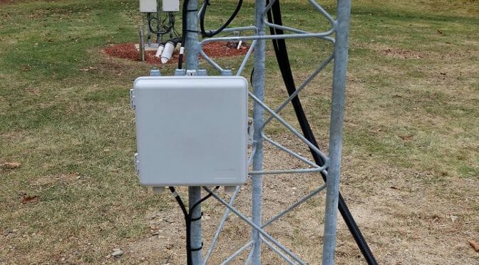
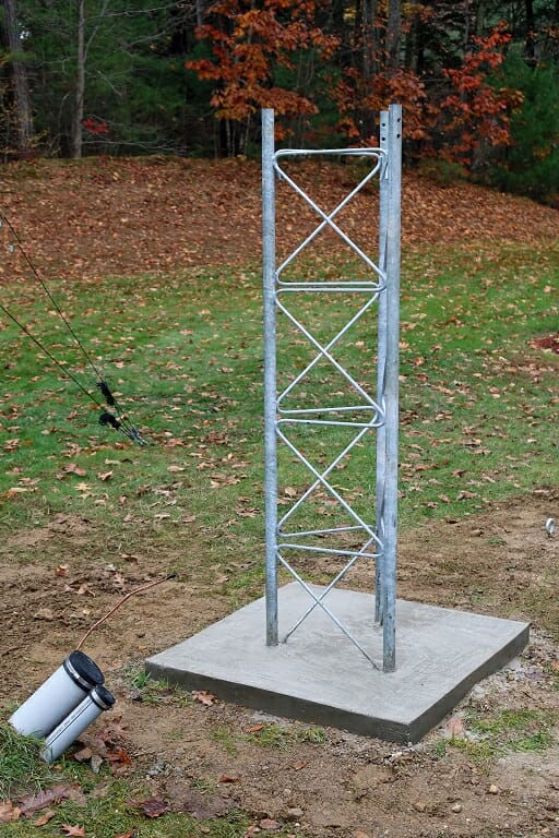
Snow is coming to New England this weekend so we wanted to get the control cables run to our new EME Tower before the ground is covered with snow. The project involved installing a Utility Enclosure…
We made some more progress on our 2m EME Station Project this past weekend. We began by installing a Utility Controller on our new EME Tower. With this done, we next ran three control cables through the conduits between our shack and the Tower. The control cables connect to our Azimuth Rotator, Elevation Rotator, and a planned MAP65 Switching and Preamp System.
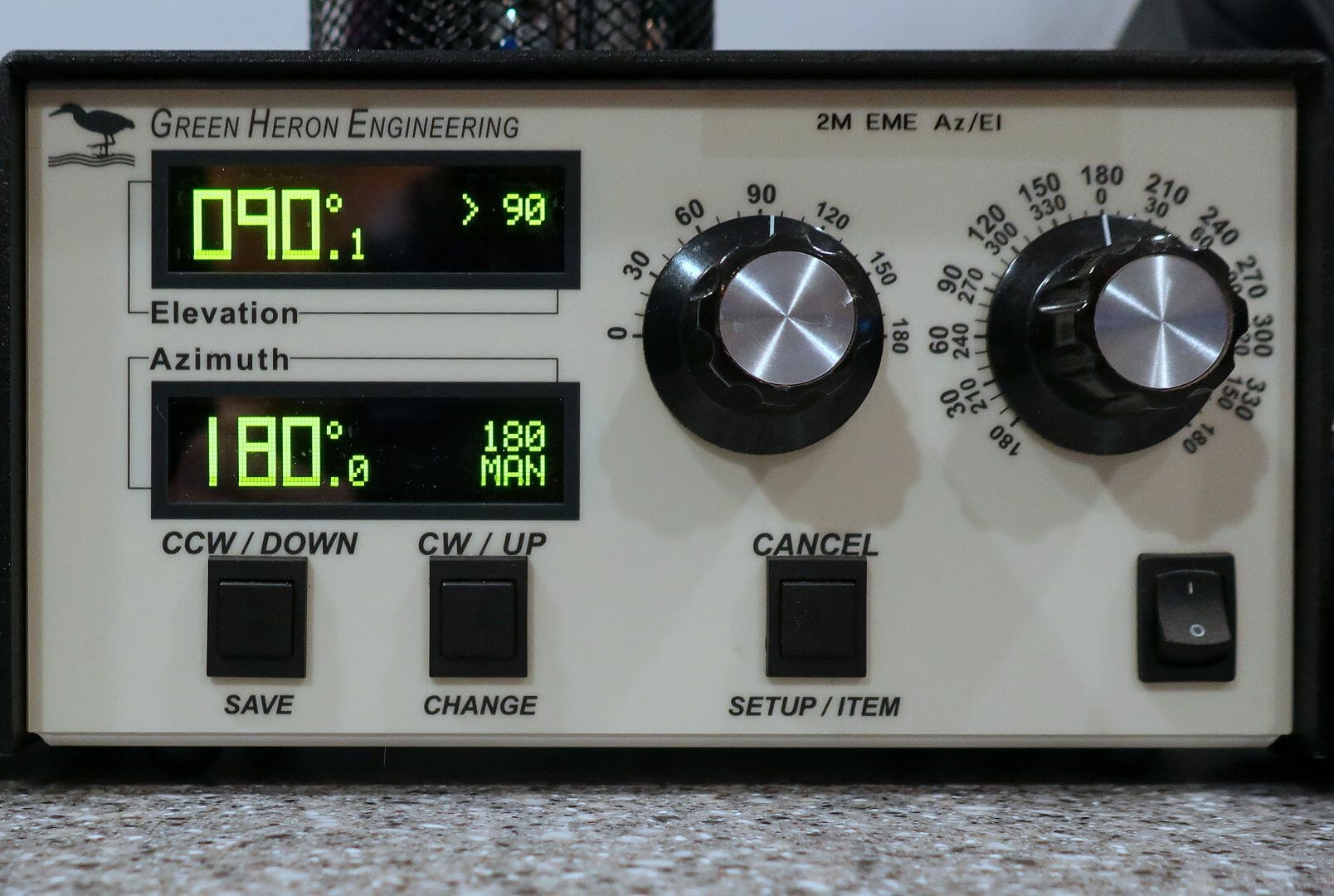
Green Heron Az-El Rotator Controller
With the cables run, we connected our Azimuth Rotator to a Green Heron Az/El Rotator Controller in our shack. This enabled us to get our Azimuth Rotator configured and tested.
The next step in our EME Station Project will be to assemble the antennas that we have on order from M2 Antennas Systems and install them along with an H-Frame and related gear on our new Tower. We are hoping that the winter weather will allow us to get this done before spring.
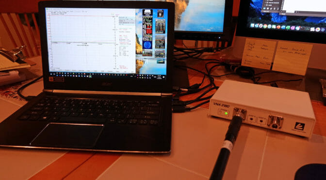
Our new 2M EME station will have Adaptive Polarity capability via MAP65. MAP65 requires that received signals from the Horizontal and Vertical planes of our antennas arrive at the receivers in our shack precisely in phase with each other. We used a VNA to precisely measure coax cable length…
We are continuing to make progress on our new 2M EME Station. The MAP65 adaptive polarity aspect of our plans requires that the phase relationship between the Horizontal and Vertical elements of our antennas be precisely maintained by our receive coax cables.
The construction of these coax cables required us to use a Vector Network Analyzer (VNA) to precisely measure and equalize the electrical lengths of our receive-coax cables. We know that a 1/4 wavelength section of coax cable which has an open-circuit at one end will appear as a low (resonant) impedance at the opposite end. If we use a VNA to precisely measure the minium resonant frequency of our coax cables in this way, we can use a simple formula to determine the cables’ lengths.
The article associated with the link above explains how a VNA can be used to measure the length of a coax cable. A frequency accurate antenna analyzer can also be used to make these measurements.
The first part of our EME project is to put up a new tower to support our antennas. Our plans call for a 26′ tower built using three Rohn 55G tower sections. Four feet of the first section of…
