I wanted to share some information about the work that I have been doing as ARRL New England Division Director for the past 3 years. I have a long history of helping people to become licensed, learn new skills, and become active in the Amateur Radio Service. Like most Hams, I love Ham Radio and all that it enables. As your director, I have worked hard to protect and grow our hobby, and I will continue to work to create and promote activities and programs that maximize our ability to participate in and enjoy Amateur Radio.
Amateur Radio changes people’s lives for the better. It certainly has had a huge positive impact on my life, and I want to continue as your director so that I may work with the ARRL, clubs, and individual Hams across New England to help bring positive life experiences through Amateur Radio to more people in our division and across the ARRL.
Action-Oriented Leadership
It is not enough to just listen to members about their concerns. While doing this is an essential part of serving as director, we also need a director who works hard to ensure that effective action is taken to address member concerns. This requires a leader who can collaborate with people to create consensus around solutions to problems and create the will to act.
Through my work as part of numerous work efforts within the ARRL, we have enabled the ARRL board and HQ team to:
- Bring forward multiple new ham development initiatives.
- Provide clubs with resources to do important work to strengthen their future and the future of Amateur Radio and the ARRL.
- Develop publications and programs to encourage increased utilization of our Amateur Radio bands and privileges.
- Revitalize the National Traffic System
- Create an ARRL strategy that includes an expanded focus on Science, Technology, Engineering, and Math (STEM) learning in schools.
We’ve also built teams here in New England to solve RFI problems and encourage the use of our bands above 1 GHz via Amateur Radio Emergency Data Networks (AREDN).
What I Want To Continue To Accomplish as New England Director
Much needs to continue to be done to create a strong future for Amateur Radio and the ARRL. The following are some of the major goals I will continue to focus on as Director:
- Bringing new people into Amateur Radio by working collaboratively with clubs across New England and the ARRL. We have also created multiple new Ham Development initiatives within the ARRL that support bringing new people into Amateur Radio.
- Expanding ARRL’s work to support STEM learning in schools through Amateur Radio
- Creating positive public and agency awareness and support for Amateur Radio to protect our spectrum and our rights. The ARRL must also continue to expand member support for initiatives to protect our spectrum.
- Ensuring effective, open, 2-way communications between the ARRL and its members and creating a culture within the ARRL to act on member concerns and feedback.
- Continuing to establish the New England Division as a leader in developing world-class Amateur Radio programs that help our members enjoy Amateur Radio.
I believe that I bring the right Amateur Radio and professional experience, as well as the necessary collaborative leadership skills, to accomplish these goals and more. I hope you will support me as your choice to fulfill this important mission.
Walking Our Talk
As your Director, it is essential that I work to support the initiatives that I advocate for within the ARRL. This enables the creation of and member support for effective policy through credible leadership.
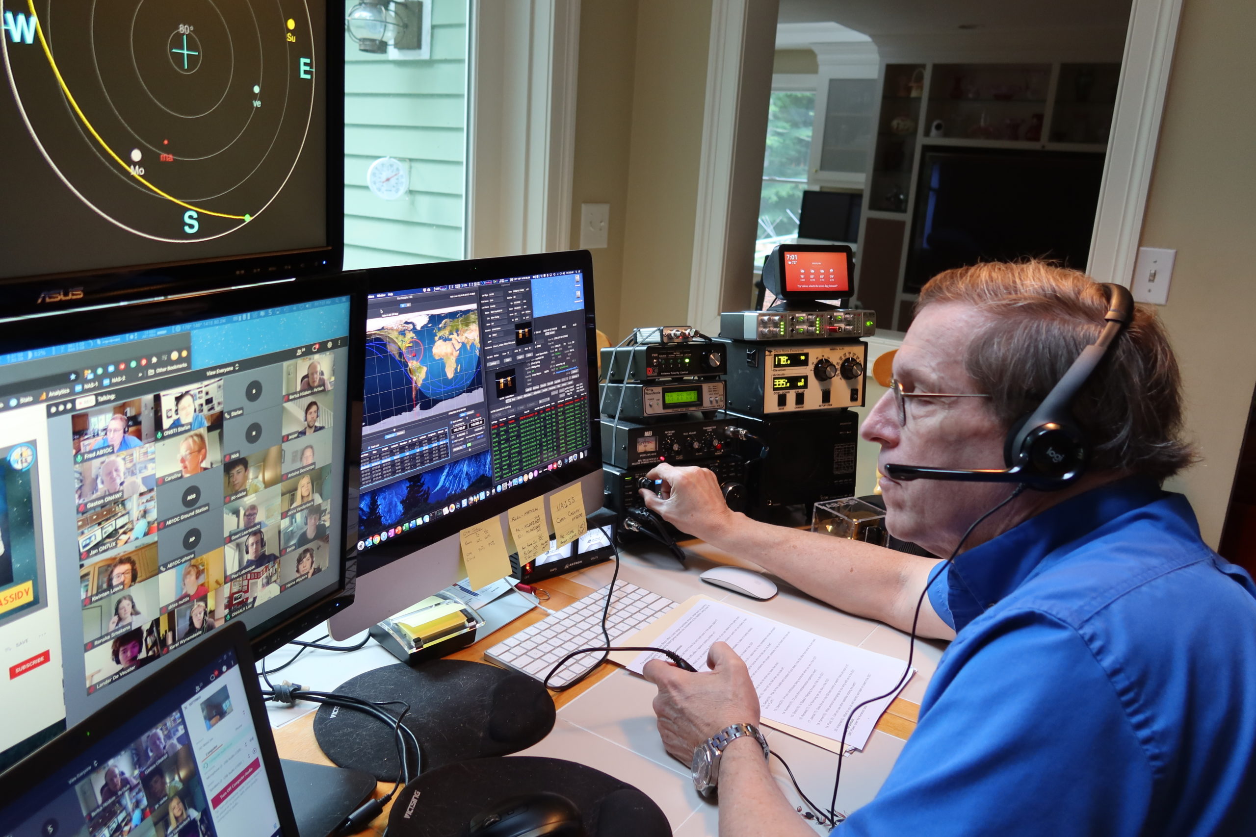
I serve as an ARISS (Amateur Radio on the International Space Station) Mentor and Ground Station, helping schools worldwide to participate in STEM learning based on Amateur Radio. I also devote considerable time and energy to licensing hams and helping them get on the air. Thanks to the help and support of a very dedicated team of Nashua Area Radio Society members who I’ve had the pleasure to work with to teach classes for Tech, General, and Extra licenses, we’ve enabled over 480 people to earn a license or upgrade over the past seven years. As part of a group of Nashua Area Radio Society members, we’ve also created a popular program called Ham Bootcamp that helps new and experienced hams get on the air, build stations, and participate in operating activities. Ham Bootcamp has helped over 1,000 people across the United States to begin or expand their participation in Amateur Radio.
As New England Division director, I have continued to work with clubs and individuals in New England to help them expand their role as mentors and create a world-class environment for learning based on Amateur Radio.
Additional Information
I have been widely endorsed by members of the Amateur Radio community for my work. You can see what others are saying about their support for me as ARRL New England Division Director at re-elect.ab1oc.org/endorsements. You can learn more about me and my Amateur Radio activities at re-elect.ab1oc.org/about-ab1oc. I welcome everyone’s comments and questions. You can reach me at [email protected].
I Need Your Support
Voting information will be distributed to New England Division ARRL members by October 1st via e-mail and postcards. Ballots are due by November 15th. Your vote means a great deal to the future of Amateur Radio.
I am asking you for your support and your vote to enable me to continue working on your behalf to benefit Amateur Radio folks across New England and the ARRL.
Fred, AB1OC


