Introduction
This article will demonstrate how a simple logic problem may be solved using Boolean algebra.
Background
In the late 1950’s through the early 1970’s something called “New Math” [1] was introduced into grade school curricula under an initiative from the National Science Foundation (NSF). However, New Math was a misnomer, and nothing could be further from the truth. The math wasn’t new at all. It was just that an NSF committee had decided to introduce the elements of something called symbolic logic to school children. The elements of symbolic logic had been taught in college-level mathematics and philosophy courses for at least 175 years! Some of us even used a text, Symbolic Logic [2], written by the student of Bertrand Russell [3], Irving Copi [4].
During the cold war, it was thought that an introduction to the idea of logical reasoning would be more beneficial to young students than rote learning [5]. It was perceived that the United States had fallen horribly behind the Soviets in the areas of science and mathematics [6]. While that may have been the case, it turned out that in attempting to teach these more advanced concepts to the young, it may have set a backward trajectory for math and science education for many years to come.
Sensing that something was missing from my school curricula in 1963; I audited a summer school algebra course being taught in the neighboring town. It featured New Math. Having been schooled in Old Math; I soon understood of how little use New Math would be, i.e., until I began to play with logic circuits. The next time I saw the material was when I took a course in digital logic about 12 years later.
As I think back, maybe the time spent teaching New Math would have been better spent teaching a few skills in critical thinking? By the 1970’s New Math had been, ironically, supplanted by Old Math, and textbooks that illustrated Venn diagrams on the covers had largely vanished.
As the late Tom Lehrer [7] of MIT (and later of UC Santa Cruz) sardonically reflected in his song lyrics:
New math, new-hoo-hoo math,
It won’t do you a bit of good to review math!
It’s so simple, so very simple,
That only a child can do it!
Enter George Boole
George Boole was a self-taught philosopher, mathematician and logician who served as the first professor of mathematics at Queens College, Cork, Ireland, in 1849 [8].
If you suffered through a course in symbolic logic, Boolean Algebra would have been one of the topics along the way.
Boolean logic symbols, and logic symbols in general, differ somewhat from those of grade school mathematics. For example, the plus symbol (+) stands for the logical symbol “OR”. We won’t have to introduce the added complexity of the OR symbol in this paper but it is really not hard to use. The dot symbol ( · ) that normally stands for multiplication stands for “AND”. This symbol along with something called an inverter will be used to solve the logic problem described in this paper. An inverter has the property that whatever is present at the input appears inverted at the output.
The Logic AND Gate
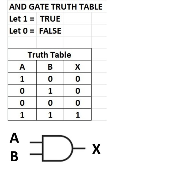
The logic AND gate is represented by the symbol shown in Figure 1. An accompanying truth table for the AND gate is also shown. What is important to remember about AND gates is that if any statement is false, the whole statement is false. This may be inferred from the truth table. The cases shown are,
1. A is true and B is false; the ANDing of the two, X, is false,
2. A is false and B is true; the ANDing of the two, X, is false,
3. A is false and B is false; the ANDing of the two, X, is false, and
4. A is true and B is true; the ANDing of the two, X, is true.
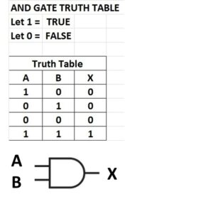
Figure 1. The Logical AND Gate. If either of the inputs, A or B, is false, the output, X, is false. Please click on the figure to open it in a new window.
The Logic Problem to Be Solved
A QRP radio is under construction and Rick, N3FJZ, is the author of the software that operates many features of the radio and the display. Rick maintains a website [9] as well as a YouTube channel [10]. Both sites are dedicated to homebrewing.
Since the software was intended for SSB operation, not CW, there is a logic state that is disallowed whenever band privilege restrictions are not entered as part of initial software setup. CW operation was never intended to be part of software setup [11].
There are two distinct modes of operation: general coverage receive and ham band transceive. If the receive frequency is set to anything other than a ham band, a general coverage command is asserted by the software. This command will switch out the low-pass filters, the power amplifier, and the band-pass filters. In their place, the command injects a bypass path around them. It is when the radio is in this state that Push-to-Talk (PTT) may be asserted, and the power amplifier will be biased. This should be disallowed.
A Possible Hardware Solution
Instead of modifying the code, a simple hardware modification is possible that will lock out the disallowed transmit state for the radio in general coverage mode.
It is known that a filter bypass flag appears on one of the Arduino microcontroller pins when the radio is tuned to anything other than one of the ham bands.
It is also known that a PTT flag appears on one of the Arduino microcontroller pins when the microphone PTT button is pressed or the PTT button on the control panel is pressed.
If we could use the filter bypass flag to inhibit transmit PTT whenever the radio is tuned to general coverage, the problem would be solved.
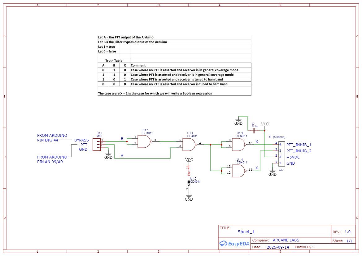
Figure 2 shows a truth table for the hardware solution for the problem as it is understood.
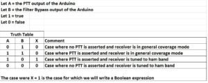
Figure 2. A Truth Table That Shows the Hardware Solution for the Problem as It Is Understood. All possible states of the PTT switch are shown in column A. All possible states of the Filter Bypass General Coverage command are shown in column B. Only one output state of X should be permitted. That is the one for which PTT is asserted and the radio is tuned within a ham band, either a SSB segment or a CW segment. All other cases shown in the truth table should be inhibited. Please click on the figure to open it in a new window.
The truth table in Figure 2 may be reduced to a single logical equation since we are only interested in the case for which X = 1. (any letter with a bar above it is the inverse of logical one, or zero). Thus,

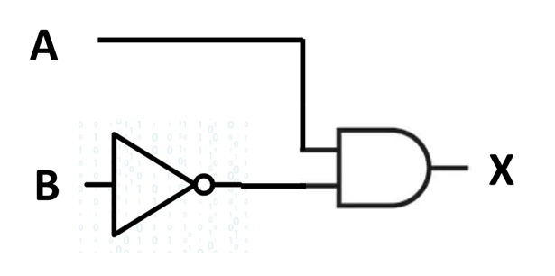
This is read as A and B-bar equals X. The logic symbol that represents this is shown in Figure 3. Here we have drawn the symbol of a logical inverter to invert the symbol, B, to make it B-bar.
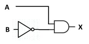
Figure 3. Simple Logic Circuit That Will Solve the Problem. For the single case of interest, A enters one of the AND gate inputs directly while B is inverted by an inverter gate so that it becomes one, or true, at the other AND gate input. We are not finished with the circuit because it would involve the purchase of two types of gates, and that seems wasteful because an inverter gate and an AND gate would be required. Please click on the figure to open it in a new window.
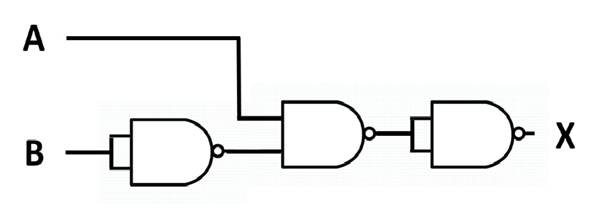
Let’s see if this circuit can be implemented with NAND gates. A NAND gate may be thought of as an AND gate whose output has been inverted. Thus, we can implement Figure 3 with NAND gates as shown in Figure 4. An inverter gate may be created by tying the two inputs of a NAND gate together. As an exercise, try applying all of the A and B inputs in the truth table of Figure 2 to Figure 4 to be convinced that this logic diagram will work. One way of looking at it is to observe that we have a NAND gate that has been inverted. That produces an AND gate. Thus, Figures 3 and 4 are equivalent.
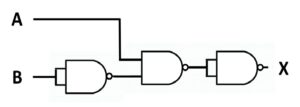
Figure 4. The Logic Diagram Of Figure 3 Implemented With NAND Gates Only. This may be implemented with a single 14-pin dual inline package (DIP) or surface mount package (SMP). The gates come four gates to a package so the extra gate may be used for an extra output or it may be tied high, if unused, to prevent it from toggling. The CD4011 would be ideal for this project because of its wide supply voltage range. Please click on the figure to open it in a new window.
Printed Circuit Board Layout
A printed circuit board layout was completed for a single CD4011 Quad NAND gate on the free, easy-to-use EasyEDA online graphics package [12]. The board is being fabricated by JLCPCB [13] for rapid turnaround. The schematic diagram is shown in Figure 5. A 3-D rendering is shown in Figure 6. The total board area is approximate 1 square inch, and it will fit nicely onto the corner of the front panel PCB as a mezzanine board. There, it will connect directly to the Arduino MEGA 2560 to perform the lockout function.
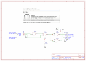
Figure 5. Transmit Lockout PCB. The schematic was completed on the easy-to-use EasyEDA online graphics package, as was the Gerber file for PCB fabrication. Please click on the figure to open it in a new window.
.
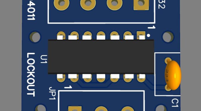
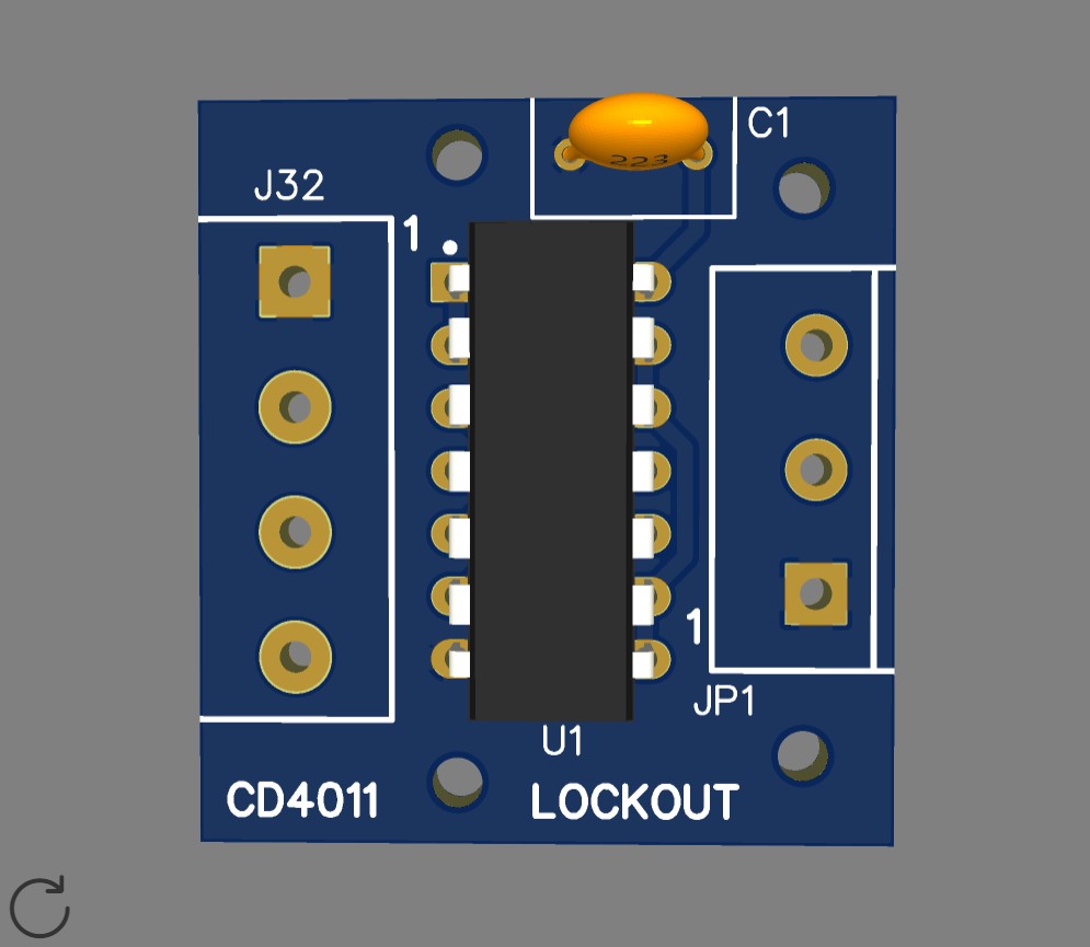
Figure 6. The CD4011 Quad NAND Gate 3-D PCB Layout. A single CD4011 Quad NAND gate is all that is necessary to implement the transmit lockout during general coverage mode. The screw terminal strips do not appear in the virtual rendering because they were unavailable in the library. Please click on the figure to open it in a new window.
References
[1] New Math, https://en.wikipedia.org/wiki/New_Math
[2] Russell, Bertrand, https://en.wikipedia.org/wiki/Bertrand_Russell
[3] Copi, Irving, Symbolic Logic, 5th ed., Pearson, 1 Jan 2015.
[4] Copi, Irving, https://en.wikipedia.org/wiki/Irving_Copi
[5] Rote Learning, https://en.wikipedia.org/wiki/Rote_learning
[6] Sputnik, https://news.harvard.edu/gazette/story/2007/10/how-sputnik-changed-u-s-education/
[7] Lehrer, Tom, https://en.wikipedia.org/wiki/Tom_Lehrer
[8] Boole, George, https://en.wikipedia.org/wiki/George_Boole
[9] Scott, Rick, N3FJZ, Circuit6040 website, http://www.remmepark.com/circuit6040/
[10] Scott, Rick, N3FJZ, Circuit6040 YouTube Channel, https://www.youtube.com/results?search_query=circuit6040
[11] Scott, Rick, N3FJZ, Circuit6040 YouTube, Module # 110 Front Panel MEGA Quick Start – MAX-SSB Transceiver Project, https://www.youtube.com/watch?v=5a9tlg8SIrk
[12] EasyEDA, https://easyeda.com/
[13] JLCPCB, https://JLCPCB.com/
Disclaimers
These circuit designs are provided for informational and educational purposes only and are supplied “as is” and without warranties of any kind, express, implied, or statutory. No representations or warranties are made regarding the accuracy, adequacy, completeness, legality, reliability, or usefulness of this information, either in isolation or in the aggregate. These circuit designs may contain links to or information based on external sources or third-party content. Endorsement and responsibility for the accuracy or reliability of such third-party information or for the content of any linked websites are not taken.