Tag Archives: Antennas

Temporary 20m EFHW Vertical Installation

I’ve been off the air since moving back to NH in 2020. Since the landscaping has not been completed on the property, it has been impossible to install the radials for a  6-BTV vertical. Radials don’t fare well under the treads of a Bobcat.

A collection of single-band, matched, end-fed half-wave (EFHW) antennas was constructed while I was living in FL. All of these antennas underwent testing on an antenna range consisting of three 10m tall masts spaced 70 ft apart.  These antennas were matched with L-networks. The test results were reported in a separate article[1].

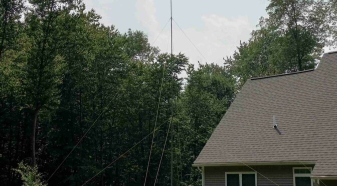
Seeing that July 4th weekend was approaching, I was eager to get on the air for a few days before the landscaper arrived. I decided on a 20m EFHW vertical that makes use of some of the guy ropes that were prepared for FL antenna testing. Figure 1 shows the installation of the 12.5m high telescoping fiberglass mast.  The mast is anchored with a tilt-over base mounting plate described in a separate article[2]. Guying is provided at two levels. The guying radius is 25 ft. Guy anchoring is accomplished with polycarbonate Orange Screws[3]. While these anchors work well in FL sand, they do not work quite as well in rocky New England soil. I managed to snap one of them off in the process of screwing it into the ground.

My favorite knot for adjusting the guy rope tension is the taut-line hitch. I used the taut-line hitch on the FL antenna range for three weeks, and the anchor screws came loose before any of the taut-line hitches did.

20m end-fed half-wave (EFHW) vertical

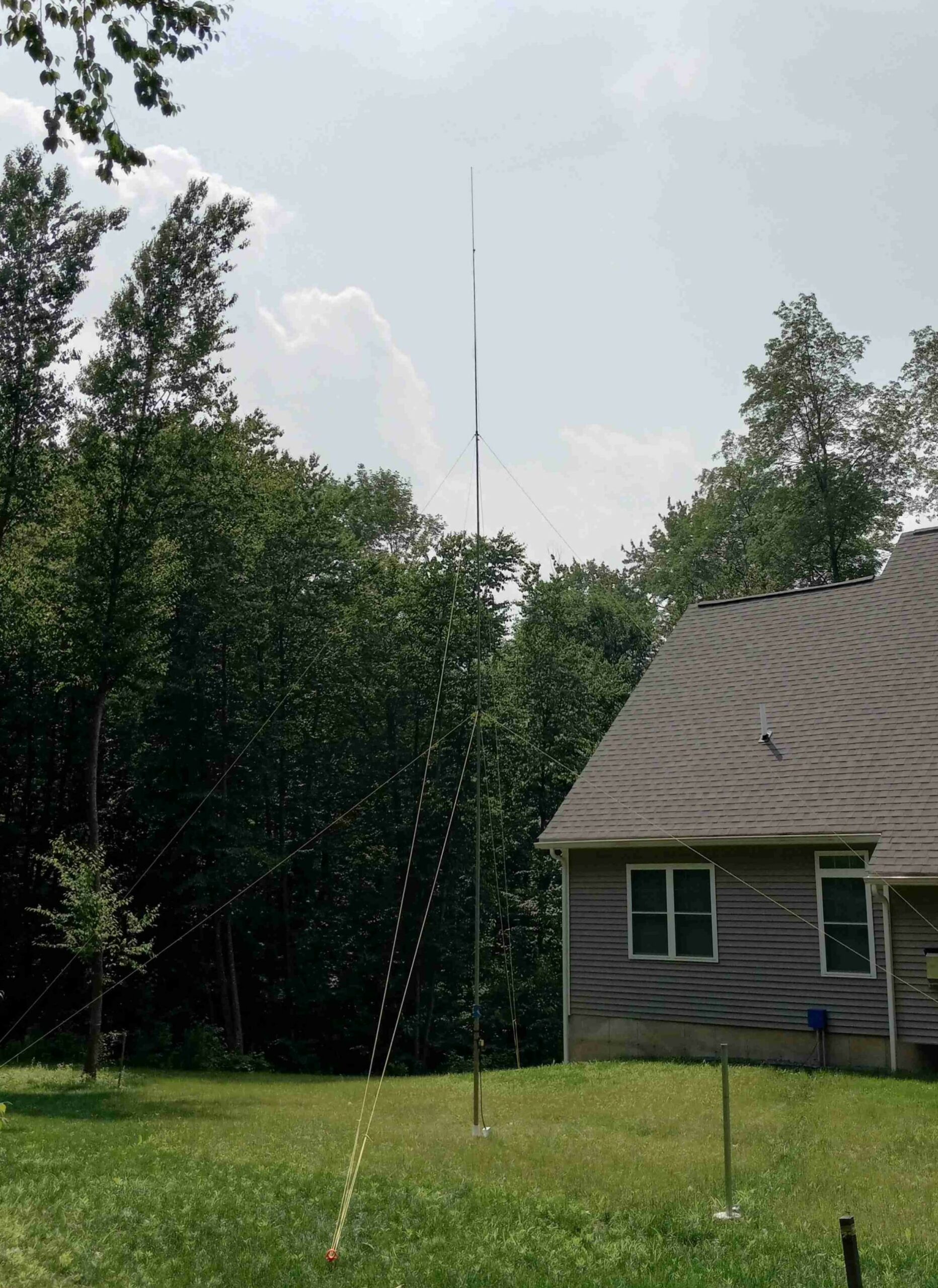
Figure 1. 20m L-Network Matched EFHW Vertical. The wire antenna and matching network is fastened to the fiberglass mast with rubber bongo ties. The mast height is 12.5m (41 ft). Base anchoring is accomplished with a hinged, tilt-over base mounting plate that was described in another article. Please click on the photo to enlarge it.

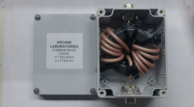
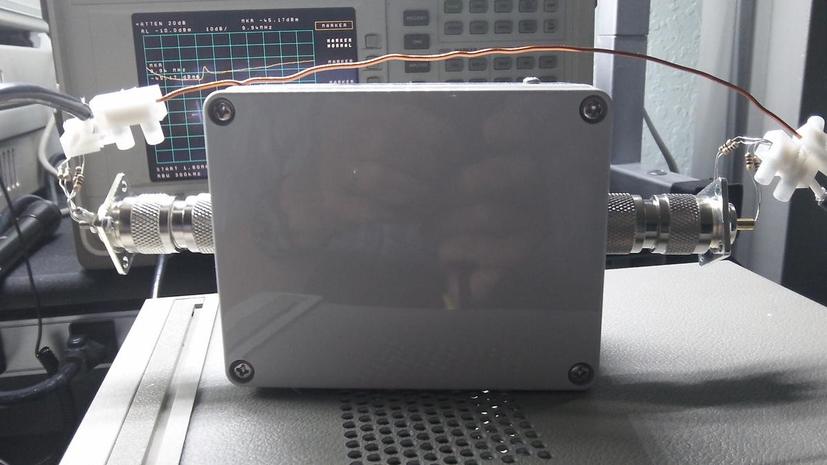
The antenna counterpoise consists of a 3 ft (~ 1m) section of outer coax shield, Figure 2. A line choke is inserted after this 3 ft section of coax to terminate the counterpoise. The remainder of coax to the shack is made up of a 40 ft long section of RG-8X.

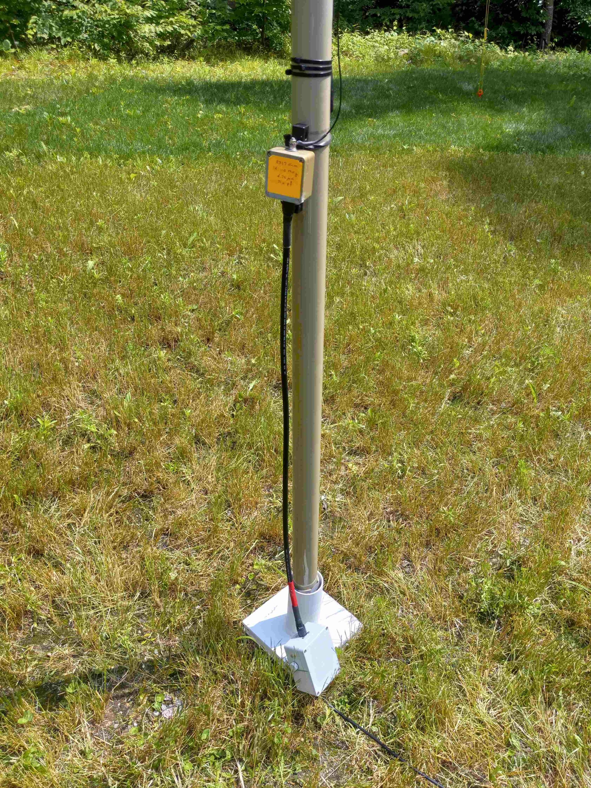
Figure 2. Matching Network, Coaxial Shield Counterpoise and Line Choke. The matching network was designed for 14.1 MHz. Since the matching network has a wide bandwidth, the antenna wire was cut slightly longer to resonate at the very bottom of the CW band. Please click on the photo to enlarge it.

A Smith Chart is plotted in Figure 3. It shows that the antenna match over the entire band is well within the 2:1 VSWR circle.

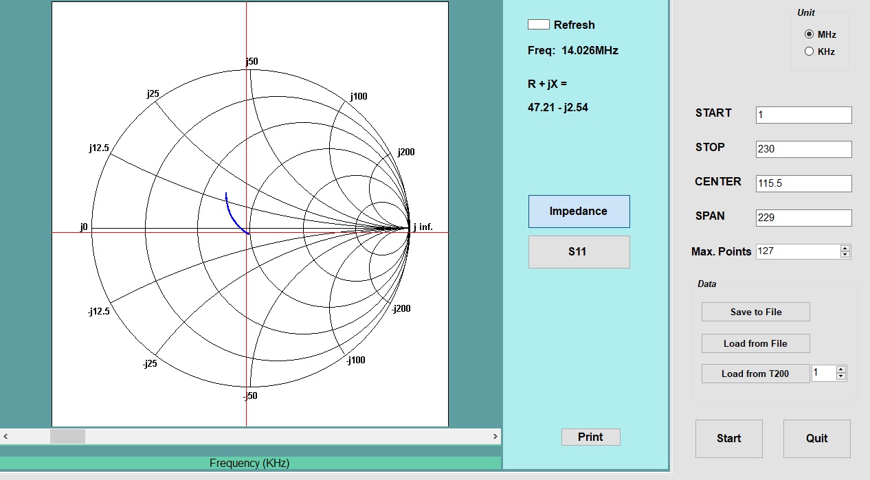
Figure 3. Smith Chart for 20m L-Matched EFHW Antenna. A match better than 2:1 match is achieved over the entire 20m band. The antenna wire was cut longer to provide the best match at 14.025 MHz. Please click on the photo to enlarge it.

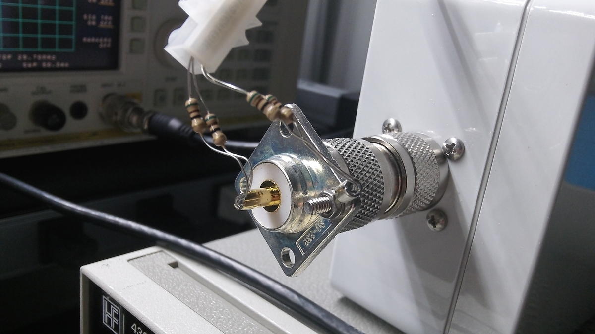
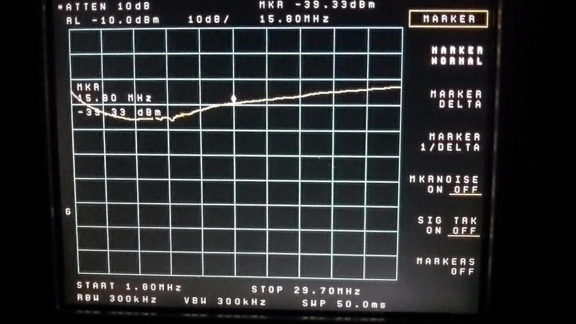
The VSWR performance is plotted in Figure 4. The matching network consists of a lowpass L-network consisting of a series inductor followed by a shunt coaxial capacitor. The antenna wire has been cut to resonate at 14.025 MHz since I enjoy operating in the bottom 50 kHz of the 20m CW band. It’s not that the VSWR performance was that bad but I just could not understand why the antenna wasn’t achieving a near-perfect 1:1 match. I turns out that the residual mismatch is in the Polyphaser lightning arrestor located in the service entrance panel.

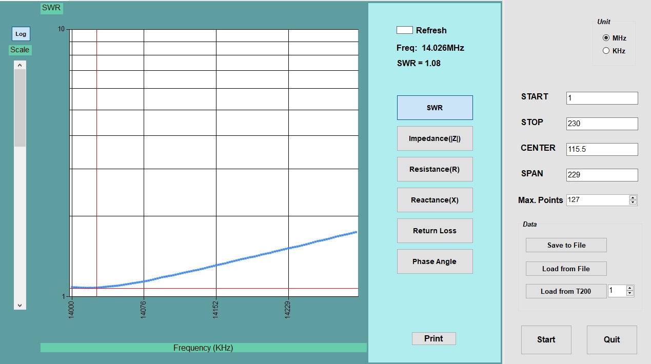
Figure 4. 20m VSWR Plot. The L-matching network exhibits wide bandwidth and good efficiency. The antenna wire is cut to resonate at the very bottom of the CW band where I like to operate. The match is very good but not perfect. This was due to the residual VSWR in the lightning arrestor located in the service entrance panel. Please click on the photo to enlarge it.

I operated a simple station consisting of an ICOM 718 at 100W to make three consecutive CW contacts with French stations. The next three days should produce some interesting DX.

References

[1] Blustine, Martin, Highly Efficient L-Matching Networks for End-Fed Half-Wave Antennas, June 11, 2022. https://www.n1fd.org/2022/06/11/l-matching-networks/

[2] Blustine, Martin, Tilt-Over Bases for Antenna Masts That You Can Build, June 30, 2022. https://www.n1fd.org/2022/06/30/tilt-over-bases/

[3] https://www.orangescrew.com/

Bob Heil to Speak to Nashua Area Radio Society on March 7th

Our March Membership Meeting will feature Dr. Bob Heil, K9EID.  Bob will speak to us about Antennas and Installation Techniques and Radio Settings .

Ham Nation
Ham Nation

Dr. Bob Heil is well know to amateurs as the former host of Ham Nation and the founder of Heil Sound.

Heil Sound makes world class Ham Radio and Professional audio equipment including headphones, microphones, and related equipment.

Heil Talk Box
Heil Talk Box

But did you know that Bob has made a name for himself in the world of Rock and Roll? He has created touring sound systems for several rock and roll bands such as the Grateful Dead and the Who.  Bob invented the Heil Talk Box, which was used by many rock and roll musicians.  He even has a display at the Rock and Roll Hall of Fame!

Bob Heil Organist
Bob Heil at the Organ

An accomplished organist, Bob played for us at the end of meeting the last time he visited us.  You can see the recording on our Videos page – look for the March 2022 Membership Meeting.

Bob Heil is a great storyteller and his previous visits to the Nashua Area Radio Society were truly memorable.  Don’t miss Tuesday’s meeting.

To learn more about Bob Heil and his incredible accomplishments, visit his QRZ and Wikipedia pages.

The membership meeting will take place on Tuesday March 7th starting at 7:00 pm. It will be a hybrid meeting, at the Nashua Library in the NPL Theater as well as on Zoom.  For more information, including the Zoom link, see our main page and scroll down to the section titled Plans for Online Meetings and Tech Nights.

Differential and Common Modes on Transmission Lines – Part III

Introduction

In Part I of this three-part series, differential and common modes on RF transmission lines were defined and discussed.

In Part II of this article, the work of Gustav Guanella was chronicled, followed by Joe Reisert’s improvements to Guanella’s original design. The construction of a common mode choke was presented that included data for the coax used. Finally, some analyses were performed that predicted the performance of two common mode chokes. Graphical results were reported.

In this final Part III, the results of measurements performed on two common mode chokes are presented: one for 2 x FT240-31 stacked ferrite cores and another for 2 x FT240-43 stacked ferrite cores. Due to its higher initial permeability, it was expected that low-frequency choking performance for the 2 x FT240-31 material would be superior to that of the 2 x FT240-43 material. We found that this was not the case for the single sample of 2 x FT240-31.

Discussion

Two coaxial line chokes were constructed to suppress common mode currents on transmission lines. Common mode currents are apt to find their way back to the operating location on the coax shield. Common mode currents can create performance problems in the form of added receiver noise and operator problems in the form of RF bites. The choking impedance should be located at a voltage node in the feedline where the wave impedance of the standing wave is low.

The coaxial line chokes were constructed on stacked cores of FT240-31 and FT240-43 material, as the literature recommends both for EMI suppression. Eleven turns of RG-400/U coax were wound on each of the stacked cores with the Joe Reisert, W1JR, crossover winding located in the center. Each choke was housed in a connectorized Bud Industries PN-1323 box. The common mode rejection for each choke was measured with a spectrum analyzer over a 1.8 to 29.7 MHz bandwidth. The spectrum analyzer tracking generator output was split into two in-phase signals that fed the choke coax center conductor and the choke coax braid in true common mode. The resistive divider formed with two 25.5-ohm resistors (made with 51-ohm resistors in parallel) is shown in Figure 1. The divider was fed in the center by the tracking generator and the ends of the 25.5-ohm resistors fed the center conductor of the coaxial connector and the connector shell. There was a similar arrangement at the output so that the spectrum analyzer could measure the resulting common mode rejection. The conduction path of the test cable shield was carried from input to output on #16 AWG as shown. Figure 2 shows the device under test. Some undesired responses were due to some nearby equipment, coax and line cords. The distance between the test coax shields also presents some challenges, and an interconnection bridge is shown that consists of a rather long piece of #16 AWG wire. After moving some cables, line cords, and equipment around, some useful data was collected. Figure 1 – Feeding the Common Mode Choke in Common Mode. A resistive power divider was constructed that consisted of paralleled 51-ohm resistors to make two 25.5-ohm resistors. The center conductor of the choke coax and the choke coax shield were fed with in-phase signals from the spectrum analyzer tracking generator. Figure 2 – Recombining the Common Mode Signals. Similarly, a resistive power combiner was constructed at the choke output that consisted of paralleled 51-ohm resistors to make two 25.5-ohm resistors. The in-phase signals from the center conductor of the choke coax and the choke coax shield are recombined and fed to the spectrum analyzer input. The shield from the input coax and output coax is bridged with a piece of #16 AWG copper wire as shown.

The reference level of the spectrum analyzer was set for -10 dBm and all measurements were made relative to that level. The first screenshot is for 11 turns of RG-400/U wound on 2 x FT240-31, while the second screenshot is for 11 turns of RG-400/U wound on 2 x FT240-43 material. Since the toroids are wrapped with the same number of turns of RG-400/U, the #31 material, possessing higher initial permeability, is expected to exhibit a higher choking impedance at 1.8 MHz than the 43 material. This does not appear to be the case for this batch of #31 ferrite. The provenance of the #31 material is good. In any event, there is greater than 20 dB of common mode rejection for both ferrite types from 1.8 to 29.7 MHz. While the response appears to favor low frequencies for #31, the overall suppression is better for this batch of #43 material. No loss corrections have been made for the resistive power divider or resistive power combiner. Figure  -. Suppression of a 2 x FT240-31 Line Choke. The ferrite material favors the lower bands but the overall suppression is inferior when compared to that of the 2 x FT240-43 line choke. Deconstruction of the choke may disclose some defects in materials or construction. Only a single choke of this type was constructed. Figure 4 – Suppression of a 2 x FT240-43 Line Choke. The ferrite material favors the higher bands but the overall suppression is superior when compared to that of the 2 x FT240-31 line choke. Fortuitously, several chokes of this type were constructed.

Conclusions

A single choke was constructed with FT240-31 material while several were constructed with FT240-43 material because most of our operation is above 7 MHz. While the shape of the response appears to favor low frequencies for #31, the overall suppression is far greater for this batch of #43 material. These measurements will be repeated when another batch of FT240-31 material is obtained. Furthermore, it is possible that the deconstruction of the FT240-31 choke may disclose some construction or material defect.


Radio Amateurs Developing Skills Worldwide