
Summer is the time of year that many of us work on our antennas and improve our stations. Anita AB1QB and I did both of these things at our QTH this summer.

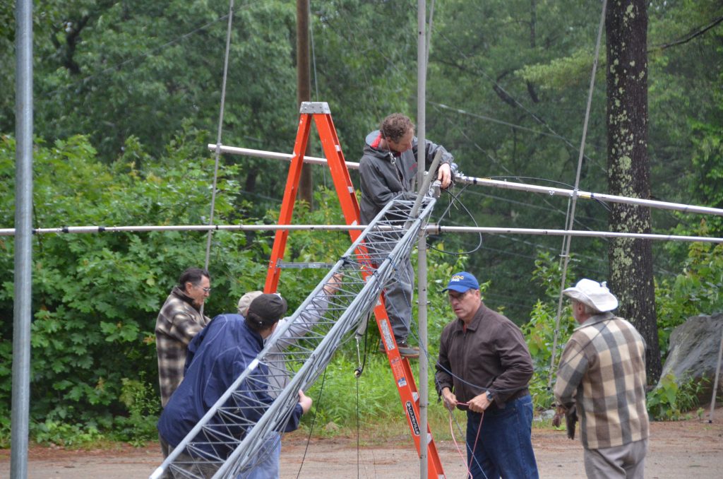
Our SteppIR DB36 Yagis were due for some maintenance so we took them off our tower. Special thanks to all the members of the Nashua Area Radio Club who helped us remove, recondition and reinstall our antennas! Matt Strelow, KC1XX of XX Towers and Andrew Toth provided equipment and know how to safely remove our two large SteppIR DB36 Yagis with help from the rest of us.

The SteppIR DB36 Yagis weigh almost 200 lbs each and Matt made good use of his electric winch to lower them.

The picture above shows the lower antenna coming off the tower. We used a Tram Line system to lower both antennas to the ground so that we could rebuild them.

The SteppIR DB36 Yagis are quite large. They have 36 ft booms and the driven elements are almost 50 ft from tip to tip! They completely fill up our back yard when they are both off of the tower.
SteppIR Rebuild

The rebuild process began with a careful inspection of both antennas. They were both in good overall condition with some sun damage to the paint on the fiberglass element poles.

We removed all the element tubes and sweeps from both antennas for rebuilding. The picture above shows the disassembled upper antenna.

All four Stepper motors on both antennas were replaced. These motors move metal tapes inside hollow element tubes to adjust the length of each antenna’s 4 movable elements. These adjustments are done automatically by controllers in our shack which receive frequency information from the radios which are connected to each antenna.

All of the element housing poles were cleaned, prepped and painted with a UV resistant clear coat to protect them from further sun damage. The poles cleaned up like new.

The assembly of all the new element sweep tubes (shown above) was done next. Each antenna has six sweeps.

The end of each element pole must be prepped with a tape system which ensures that the poles are seated properly, sealed to and firmly attached to the sweeps. This process and the associated assembly and tightening of the element couplers was the most time-consuming step in the rebuilding process as it had to be repeated a total of 24 times.

Here’s a picture of one of the rebuilt element tube assemblies. The ropes support the element tubes and keep them aligned when the antenna is up in the air. These elements are attached to the antenna motors with couplers and clamps.

The picture above shows the lower antenna with all the element tubes reattached. There is quite a bit of additional prep work associated with adjusting all the supports and taping all the exposed areas of the antennas which are susceptible to sun damage. Also, all the electrical wiring on the antenna must be checked to ensure good electrical connections and good overall condition of the wiring.
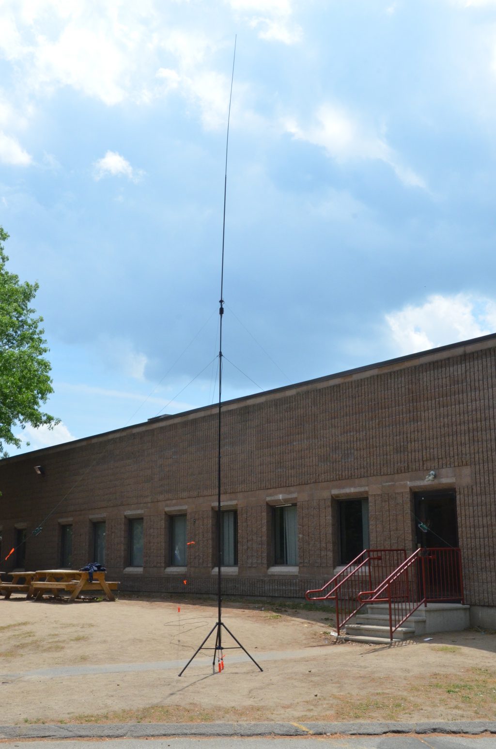
SteppIR Ground Testing

The final step in rebuilding the antennas is to test their operation on the ground. This ground test is done to ensure that all the motors are working correctly and that the element tapes move smoothly inside the rebuilt element tubes.

Another important part of the antenna Ground Test is to confirm that the antennas have a consistent resonant frequency and SWR on all bands. The resonant frequencies and SWR levels are far from those that would be measured when the antennas are on the tower at operating height. The idea here is to confirm that a resonance exists and that its frequency and SWR readings are repeatable as the antenna is adjusted to different bands.
SteppIR Installation and Final Testing
Tramming Antennas Onto A 100 Ft Tower
With both antennas rebuilt, its was time for Matt and Andrew to return and, with help from folks from our club, reinstall the rebuilt antennas on our tower. The video above shows this process. It is quite something to see! The installation took about 3 1/2 hours.

The last step in the SteppIR DB36 rebuild process was to install the latest firmware in the associated SDA100 Antenna Controllers. There were some integration issues between the updated SteppIR Firmware and our microHAM system but we are getting those worked out with help from the folks at both SteppIR and microHAM.
Transceiver Upgrade

I recently had a major birthday milestone and Anita surprised me with a new radio – an Icom IC-7851. This radio is an upgrade/replacement for our Icom IC-7800. While the two radios are quite similar in their operation and interfaces, I did not want to install the IC-7851 until the SteppIR antennas were reinstalled and all of their upgrades were working properly with our current radios. With the antennas done, it was the time to install the new radio!

The Icom IC-7851 has several important performance upgrades. The most impactful one is a new low phase noise oscillator which significantly improves RMDR performance compared to the IC-7800. The IC-7851 is in the top-tier of Transceivers in Sherwood Engineering’s tests. The receivers in the IC-7851 are very quiet, have excellent Dynamic Range and perform great in when close-in interference is present.

The Icom IC-7851 has a higher resolution and faster display. It also supports higher resolution external monitors so we installed an upgraded display monitor along with the new radio. The IC-7851 has a number of new networking features and supports stand-alone remote operation over a LAN and the Internet. We are planning to use these capabilities to add a second remote operating gateway to our station. More on this in a future article.
The combination of the rebuilt antennas and the new IC-7851 Transceiver has our station performing better than ever. The antennas are working as well or better than when they were new and the IC-7851 has significantly better receive performance compared to its predecessor and is a pleasure to use.
We will be hosting the ARRL Rookie Roundup RTTY contest for our club members who have received their first license in the last 3 years next weekend and we’re going to use the new radio and rebuilt antennas for the contest.
This project was completed in a little over two weeks and was a lot of work. I could not have done the project without the help of the many folks in our club. Again, a big Thank You to all the folks in our club who helped me with this project! I hope that many of you will be able to find some time to operate from our upgraded station.
73,
Fred, AB1OC