Our club has quite a few members who are interested in space communications. We decided to build a simple portable satellite station last year for our 2016 Field Day operation to learn about satellite communications and to create something new for folks to work with during 2016 Field Day.
Simple Portable Satellite Station
Our 1.0 Portable Satellite Station was a relatively simple setup built around an HT, an Elk 2m/70cm satellite antenna, and some gear to improve the receive performance and transmit power output of the HT. All of the gear was mounted on a board to make it easy to transport and it is powered by a LIPO rechargeable battery. The gear in our 1.0 station is made up of the following:
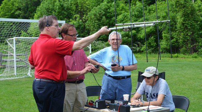
Our first contacts with our 1.0 station were made using the Elk Antenna hand-held. Later, we created a “plumber’s special” setup with a camera tripod to make pointing the antenna easier. Note the angle meter from a local hardware store which measures the elevation angle of the antenna.
AO-85 (Fox-1A) U/V Mode FM Cube Satellite
This setup worked great for making FM contacts through AO-85 (Fox-1A), a U/V mode FM EasySat. We used the 1.0 station on multiple occasions including Field Day 2016 and several of our club members used it to make their first satellite contacts. The Full-Duplex HT allowed us to hear our own signal coming back from the satellite which was an important tool to help with aiming the antenna properly. The ELK Dual-Band antenna is also a good choice because it uses a single feed point and a single polarization for both the 2m and 70cm bands.
1.0 Station Team Operating Approach
We used the team operating approach outlined above. This worked especially well for new folks who had not made a satellite contact before as it enabled each of the three team members involved in making the contact to focus on a specific part of the contact. We used orange plastic tent stakes to make AOS, Time of Closest Approach, and EOS to mark headings for each satellite pass. Small flashlights used at the stakes made them glow for night-time passes.
These goals have become the basis for building our Portable Satellite Station 2.0. More on the new station in Part 2 of this series. Other articles in the series include:
Well, another month has gone by on my two-band attic Moxon antenna project. If you recall from last month, I was left with a perplexing matching problem with the 15M antenna while the 17M one works fine. I had to figure out how to come up with a way to chase down what was causing the problem. I guess this just proves that there is no such thing as a simple, straightforward antenna project.
So, with a can of suds as brain fuel, I sat down to methodically list what to do and rule out possible causes. As a starting point, I connected a 1:1 balun to the 15M and a no-balun, connection to the 17M beam. This time, I decided to do all measurements from the shack so that losses from the shack coax would be taken into account. SWR checks on each antenna were consistent with earlier measurements, namely an SWR <2:1 on 17 and 15 meters using the 17M Moxon while rising to 4.4:1 – 6.0:1 across the band when switched to the 15M beam.
Ameritron RCS-4 Remote Antenna Switch
The next step was to rule out any leakage inside the RCS-4 remote switch. I decided to try this step because I was suspicious of the current design of the RCS-4. I had used one for about 20 years in good ol’ NH weather without a problem. The new unit, however, felt light. The relays in the remote unit were too quiet for my liking, and an AC power pack replaced the internal power supply from the old unit. I moved the 17M connection to the last position on the switch so that it was on a separate relay from the 15M antenna and measured. No change. I then disconnected the 15M antenna from the switch, leaving it open, and measured. Again, no change. I connected a jumper across the 15M connector to short the antenna elements together and measured both bands on the 17M antenna. As observed earlier, the 17M beam works fine on both bands, indicating the 17M Moxon does not see the 15M one.
OK, so now what? It was clear the 15M beam was being influenced by the 17M one. I decided to check the phasing between the two beams wherein the center and shield sides of the coax were connected to the respective sides of each beam. The casual observer will recall a demonstration by Dale, AF1T of what happens when stacked beams are fed in-phase or out-of-phase. However, since I’m operating on two different bands, why do I want to do this? The answer: electromagnetic behavior is complicated; just ask J. C. Maxwell.
To do this, I connected a center insulator that has an integrated PL-259 connector to the 15M beam. I had used this connector in the past and it was already marked for the shield and center conductor sides. I checked the balun connections that I had removed from the 15M beam, found the shield side on the first try, and marked it. I installed the balun on the 17M beam which now represented the opposite of the previous antenna connections. My rationale for doing this was that a direct, non-balun connection showed a good match on 17M.
Measurements from the shack on the 15M beam now showed an average SWR of ~3.3:1 across the band, better than before but not great. Measurements on the 17M beam when tuned to 15M, however, were clearly worse with an average SWR of 4:1. Measurements on 17M were also degraded with the SWR above 2:1. Clearly, the antennas were not happy with this arrangement. I decided to disconnect the 15M beam from the RCS-4 switch based on the noticeable change observed on the 17M beam, and remembering that the 17M beam did work before on 15 meters. When I tuned the 17M beam across 15 meters, the SWR jumped to 8:1. I was now suspicious of what effect the balun was having on antenna behavior. Why should the performance be significantly worse with a balun when compared to the simple split feed of the center insulator?
I pulled the insulator and the balun off the antennas to check the connections again. I was surprised to find that the center insulator showed an open-circuit for the center conductor side. Even more surprising was the fact that the balun showed the same thing, meaning NO CONNECTION to one side of each antenna. I looked at the lugs for each device where the center conductor was and noticed that they were loose. Furthermore, the PVC plastic around each lug had been melted from my efforts to remove old wire and solder from the lugs. Murphy, you struck again!
In desperation, I took a hacksaw to the top of the center insulator connector to check the center wire inside. I found it to be intact so I then removed the eye-bolt and replaced the lug with a new one. The connection to the PL-259 center conductor now worked. I could re-use the “topless” insulator since it would be in the attic and not exposed to rain. I scrutinized the same lug on the balun and figured the melted PVC plastic, as in the case of the center insulator, must have formed an insulation between the lug and the eye-bolt to the balun center conductor. I scrounged around the junk box and found another PL-259-equipped center insulator I could use.
I trudged back up to the attic and reinstalled the center insulators on each beam and scrambled back to the shack to measure things. This time, SWR for the 17M Moxon was flat across the 17M band vice over 2:1 before. Performance on 15 meters for the 17M beam was now down to 2.2:1 which was certainly better than 8:1. The 15M Moxon, however, still showed slightly greater than 3:1, indicating some interaction was still going on, or still a mismatch. Now what?
As I pondered what could be happening, I remembered something about RF chokes around the coax jacket to prevent common-mode interference. I recalled my education about rejecting common-mode interference from a presentation by Chuck, W1HIS, aka, Doctor “Ferrite”. Chuck is the de facto High Priest of Common-Mode Exorcism to prevent RF from entering the shack via feed lines and anything else that comes into the shack. (By day, Chuck is an MIT professor emeritus. The Dr. Ferrite title has been bestowed upon him for his prolific use of ferrite chokes throughout his house. He hates RF noise.)
Admonishing my transgression, I grabbed a couple of ferrite cores from my junk box and scurried up to the attic. I wrapped as many turns as possible of the RG-8X coax line from the shack until there was no more slack on the attic floor. I also wrapped a few turns of the coax from the 15M Moxon around a core. Sadly, there was no change when I checked each beam from the shack. Well, at least I was relieved that I did not appear to have RF sneaking back into the shack and playing tricks on me.
OK, what next? As I pondered what to do it occurred to me that the antennas were fed in-phase wherein the shield side of each antenna was the same. The logical next step was to feed them out-of-phase. I removed the center insulator for the 17M Moxon and reversed the leads so that the coax center conductor was now under the shield side of the 15M Moxon. A sweep of the 17 and 15-meter bands while feeding the 17M Moxon showed an SWR under 2:1 for each band. Switching to the 15M Moxon and sweeping the band still showed the perplexing behavior of SWR greater than 3:1. I did a sweep of several MHz above and below the 15-meter band to determine if the 15M Moxon might be resonant elsewhere but it was not.
Well, at this point it looks like I can operate two bands with the 17M Moxon so it is not a total loss. I am back to where I started in terms of performance of the antennas except the flaky balun is gone for 15 meters. I checked how the EZNEC pattern looks when operating at 21 MHz with the 17M antenna and it does not look much different from 18 MHz. On the bright side, I can always use the tuner in the K3 to make the 15M Moxon play right for the band, giving me some flexibility if I can hear a station better on one antenna than the other. Like I said, the electromagnetic behavior is a complicated phenomenon.
Anita and I like to take advantage of the mild fall weather to do antenna projects at our QTH. We have completed two such projects this fall – the installation of a Two-Element Phased Receive System and a rebuild of the control cable interconnect system at the base of our tower.
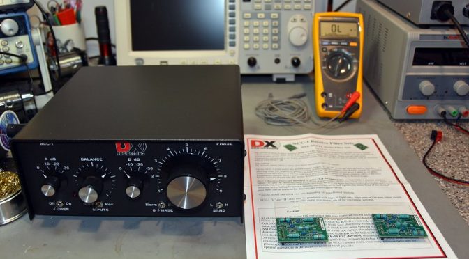
The NCC-1 System can be used to peak or null a specific incoming signal. It can also be applied to a noise source to null it out. The direction that it peaks or nulls in is determined by changing the phase relationship between the two Active Antenna Elements via the NCC-1 Controller.
NCC-1 Filter Installation
The first step in the project was to open the NCC-1 Control Unit to install a set of 80m and 160m bandpass filter boards. These filters prevent strong out-of-band signals (such as local AM radio stations) from overloading the NCC-1. The internal switches were also set to configure the NCC-1 to provide power from an external source to the receive antenna elements through the connecting coax cables.
Receive Antenna Elements and Coax
Installed Active Receive Antenna Element
The next step in the project was to select a suitable location for installing the Receive Antenna Elements. We choose a spot on a ridge which allowed the two Antenna Elements to be separated by 135 ft (for operation on 160m/80m) and which provided a favorable orientation toward both Europe and Japan. The antenna elements use active circuitry to provide uniform phase performance between each element’s 8 1/2 foot whip antenna and the rest of the system. The antenna elements should be separated by a 1/2 wavelength or more on the lowest band of operation from any towers or transmit antennas to enable the best possible noise rejection performance.
Received Antenna Element Closeup
The two Antenna Elements were assembled and installed on 5 ft rods which were driven into the ground. To ensure a good ground for the elements and to improve their sensitivity, we opted to install 4 radials on each antenna (the black wires coming from the bottom of the unit in the picture above). The Antenna Elements are powered through 75-ohm flooded coax cables which connect them to the NCC-1 Control Unit in our shack. The coax cable connections in our setup are quite long – the length of the pair being approximately 500 ft. The use of flooded coax cable allows the cables to be run underground or buried. Should the outer jacket become nicked, the flooding glue inside the cable will seal the damage and keep water out of the cable.
Receive RF Choke
It is also important to isolate the connecting coax cables from picking up strong signals from nearby AM Radio stations, etc. To help with this, we installed Receive RF Chokes in each of the two coax cables which connect the Antenna Elements to the NCC-1. These chokes need to be installed on ground rods near the Antenna Elements for best performance.
Underground Cable Conduit In Our Yard
We ran the coax cables underground inside cable conduits for a good portion of the run between the antenna elements and our shack. The conduits were installed in our yard when we built our tower a few years back so getting the coax cables to our shack was relatively easy.
Receive Antenna Coax Ground System
The last step in the outdoor part of this project was to install a pair of 75-ohm coax surge protectors near the entry to our shack. An additional ground rod was driven for this purpose and was bonded to the rest of our station’s ground system. We routed both of the 75-ohm coax cables from the two Antenna Elements through surge protectors and into our shack. Alpha-Delta makes the copper ground rod bracket shown in the picture for mounting the surge protectors on the ground rod.
Shack Installation
Antenna Equipment Shelf In Our Shack (The NCC-1 Control Unit Is At The Bottom)
The installation work in our shack began with the construction of a larger shelf to hold all of our antenna control equipment and to make space for the NCC-1. The two incoming coax cables from the Antenna Elements were connected to the NCC-1.
microHAM Station Master Deluxe Antenna Controller
Antenna switching and control in our station is handled by a microHAM System. Each radio has a dedicated microHAM Station Master Deluxe Antenna Controller which can be used to select separate transmit and receive antenna for the associated radio. The microHAM system allows our new Receive Antenna System to be shared between the 5 radios in our station.
Antenna Switching Matrix
The first step in integrating the Receive Antenna System was to connect the output of the NCC-1 to the Antenna Switching Matrix outside our shack. We added a low-noise preamp (shown in the upper left of the picture above) to increase the sensitivity of the Antenna System. The blue device in the picture is a 75 ohm to 50-ohm matching transformer which matches the NCC-1’s 75-ohm output to our 50-ohm radios. The other two preamps and transformers in the picture are part of our previously installed 8-Circle Receive Antenna System.
Protection From Overload
Multi-Radio Sequencer
The Antenna Elements must be protected from overload and damage from strong nearly RF fields from our transmit antennas. In a single radio station, this can be handled via a simple sequencer unit associated with one’s radio. In a multi-op station such as ours, it is possible for a different radio than the one which is using the Receive Antenna System to be transmitting on a band which would damage the Receive Antenna System.
To solve this problem, we built a multi-radio sequencer using one of the microHAM control boxes in our station. The 062 Relay Unit shown above has one relay associated with each of the five radios in our station. The power to the Receive Antenna System is routed through all 5 of these relays. When any radio transmits on a band that could damage the Antenna Elements, the associated relay is automatically opened 25 mS before the radio is allowed to key up. This ensures that the system’s Antenna Elements are safely powered down and grounded.
On The Air Performance
NCC-1 Controls
So how well does the system work? To test it, we adjusted the NCC-1 to peak and then null a weak CW signal on 80m. This is done by first adjusting the Balance and Attenuator controls on the NCC-1 so that the incoming signal is heard at the same level by both Antenna Elements. Next, the B Phase switch is set to Rev to cause the system to operate in a signal null’ing configuration and the Phase control is adjusted to maximize the null’ing effect on the target signal. One can go back and forth a few times between the Balance and Phase controls to get the best possible null. Finally, the incoming signal is peaked by setting the B Phase switch to Norm.
Peaked And Null’ed CW Signal
The picture above shows the display of the target CW signal on the radio using the NCC-1 Antenna System. If you look closely at the lower display in the figure (null’ed signal) you can still see the faint CW trace on the pan adapter. The difference between the peak and the null is about 3 S-units or 18 dB.
NCC-1 Used For Noise Cancellation
The NCC-1 can also be used to reduce (null out) background noise. The picture above shows the result of doing this for an incoming SSB signal on 75m. The system display at the top shows an S5 SSB signal in the presence of S4 – S5 noise. Also, note how clean the noise floor for the received SSB signal becomes when the unit is set to null the noise source from a different direction than the received SSB signal.
We are very pleased with the performance of our new Receive Antenna System. It should make a great tool for DX’ing on the low-bands. It is a good complement to our 8-circle steerable receive system which we use for contesting on 160m and 80m.
Other Antenna System Maintenance
Tower Control Cable Interconnects (Bottom Two Gray Boxes)
Our other antenna project was a maintenance one. We have quite a number of control leads going to our tower. When we built our station, we placed surge protectors at the base of our tower. We then routed all of our control leads through exposed connections on these units. Over time, we found that surge protection was not necessary. Also, we became concerned about the effects that sunlight and weather were having on the exposed connections. To clean all of this up, we installed two DXEngineering Interconnect Enclosures on our tower and moved all the control cable connections inside them.
Inside View Of Interconnect Enclosures
We began with a pair of enclosures from DXEngineering and we mounted screw terminal barrier strips on the aluminum mounting plates in each enclosure. The aluminum plates are grounded via copper strap material to our tower.
Closer Look At One Of The Interconnect Enclosures
The picture above shows one of the interconnection boxes. This one is used to connect our two SteppIR DB36 Yagi Antennas and some of the supporting equipment. The barrier strips form a convenient set of test points for troubleshooting any problems with our equipment on the tower. There are almost 100 control leads passing through the two enclosures. This arrangement keeps everything organized and protected from the weather.
With all of our antenna projects complete, we are looking forward to a fun winter of contesting and low-band DX’ing.
We use cookies to ensure that we give you the best experience on our website. If you continue to use this site we will assume that you are happy with it.


 U/V Mode FM Cube Satellite")