My main antenna is a full wave 40m delta loop which also matches well across 20m. While the match is good the pattern is not ideal for DX. EZNEC predicts numerous nodes and nulls and a high take off angle. I have been looking for a better 20m DX antenna while I wait to get a beam up.
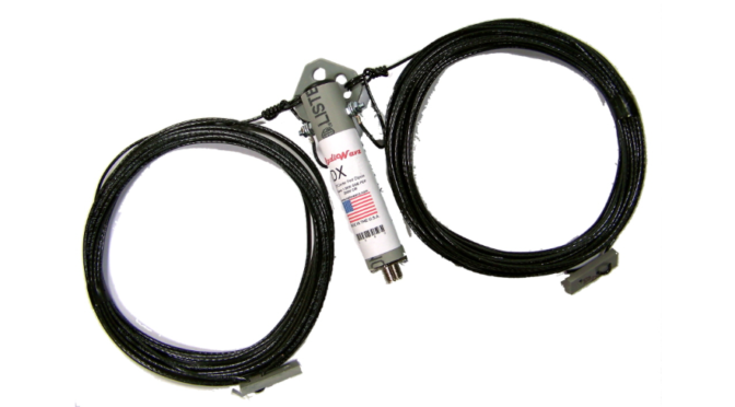
At the Club’s (N1FD) recent VE session a Radio Wavz 20m Dipole was described as having good DX performance when mounted as a vertical. At $39 including a 1:1 choke balun, I decided to try it.
I shot a rope over a branch at 65′, attached and sealed the coax, and hauled the dipole up. The coax needs to come away from the vertical at roughly 45° to minimize the coupling to the lower antenna wire.

A paracord is attached to Balun in the opposite direction from the coax to oppose the pull of the coax and is needed to keep the antenna wire vertical as shown in Figure 1.
I used a water bottle to weigh down the lower wire which allows the antenna to move with the tree to avoid damage during high winds. Figure-2 shows the Delta Loop and to its right the Vertical Dipole. It is difficult to see the Vertical, the green water bottle can be seen just below the center of the figure.
")
After the initial installation, the first step was to measure the VSWR. This can be done using the radio’s VSWR meter or an antenna analyzer. If the antenna had to be brought down to adjust its length I wanted to do it before I secured the cables and finished the installation.
The antenna analyzer measured a <1.8:1 VSWR from 13.4 MHz to 14.35 MHz. A good match over 1 MHz of bandwidth is very good. The resonate point with a 1.2:1 VSWR was at 13.9 MHz. The antenna was long which is normal “out of the package” without any tuning. With a little shortening, the match was <1.5:1 across the entire 20m band and less than 1.2:1 at band center. This is better than EZNEC predicted. The VSWR measurement includes 100′ of LMR-400 which will improve the apparent match a little. I suspect most of the improvement is from the interaction with the angled coax. It is also possible the balun isn’t a perfect 1:1 as described by Radio Wavz. The antenna has a very good match across the full band and does not need a tuner.
The vertical dipole’s noise floor was S3 (-106 dBm 3 kHz BW) which is good. I had assumed it would be much higher because it was a vertical. It is only an S unit higher than the Delta loop which measured S2 (-111 dBm 3 kHz BW).
EZNEC shows a low 10-45 degree take off angle and no NVIS capability with the top of the vertical dipole at 65′ as seen in Figure 3.

Based on EZNEC it should be better for DX than for local communications. In practice, this is the case.
For the first test, I tuned into the afternoon 20m Net. Most of the stations are within 400 miles of my QTH. The Delta Loop had a 10 dB to 20 dB SNR (signal to noise ratio) advantage at this range. An Agilent spectrum analyzer was used for these measurements. Tuning the band I found Vancouver BC, WA, OR, CA, and Ireland. Only Ireland could be heard with the Loop. I have never heard any 20m stations in the Pacific NW while using the loop.
The next test was to use the RBN (Reverse Beacon Network) to measure the antennas DX performance. For those unfamiliar with RBN, there are roughly 140 stations worldwide that are connected to CW Skimmers. Using CW you send a series of CQs and your call sign. If you are detected you are added to a Spot Collector which is accessible on a website or via telnet.
I transmitted on 14,037.5 when using the Loop and 14,038.5 when using the Vertical Dipole. By using two frequencies I could tell which antenna the Spot was reporting. Also, most of the RBN stations will not respond to a second call too soon after reporting the first intercept. With a quick QSY, I could transmit on the opposite antenna without waiting. Figure 3 is a sample of the RBN Spots.

I plotted the distance to the Spots versus the reported SNR. This can be seen in Figure-4. The number of RBN nodes is limited and some of the nodes listed on the RBN website might not be available, especially during this weekends SSB contest. Also, the band conditions will impact the range and number of stations reached.

Note that where two data points (Red and Blue) are at the same range and therefore directly above each other both antennas were spotted by the same station. If the Spot could hear the Loop it always heard the Vertical Dipole but there were many times the Spot heard the Vertical Dipole and not the Loop.
KM3T is only 3.1 miles from my QTH. As seen in the RBN screen capture and on the plot the SNR with the Vertical is 55 dB and only 45 dB with the loop. The plot also shows an SNR=9 dB data point for the Vertical near the Y axis and no matching Blue data point for the Loop. This station was 70 miles away in MA. Both of these data points rely on ground waves and the Vertical Dipole has an advantage when compared with the Loop.
Overall beyond 1000 miles the Vertical Dipole clearly performs better than the Delta Loop and will definitely add DX to a log.
In summary when mounted high the vertical dipole retains the low take off angle of a 1/4 wave ground mounted vertical. It does not need ground radials and ground losses are reduced. It can be placed above obstructions such as a barn or house. It only needs one high support and it does not require a tuner.
It isn’t a hex beam or a yagi due to the impact of ground losses on the gain, but at $40, no tower required, it is a great antenna. It is very stealthy as well.
Hamilton, K1HMS


")
