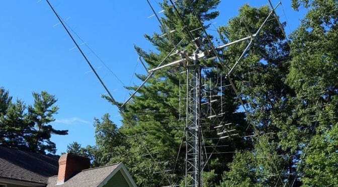
Part 1, Building the Antenna and Base
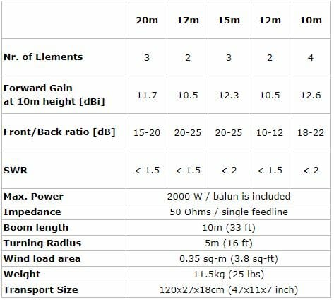
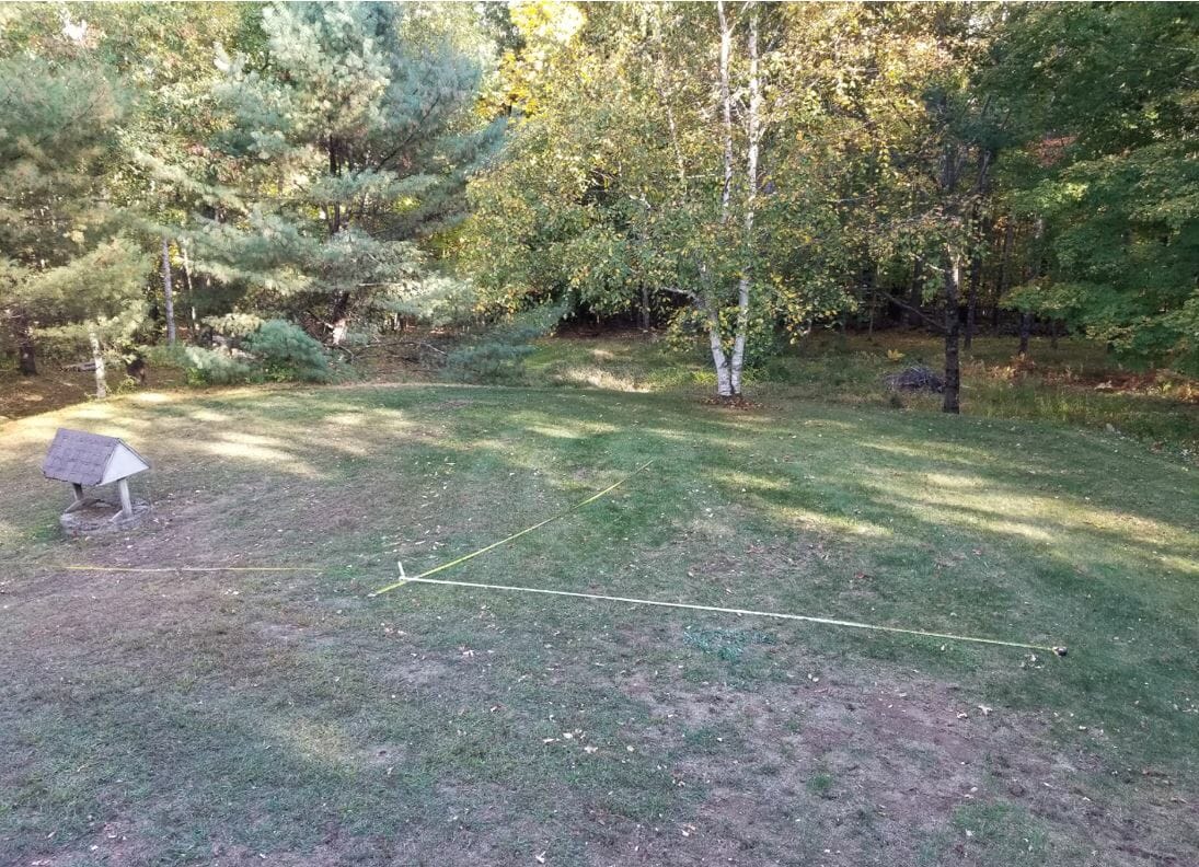
As shown in the specifications above the Spiderbeam has a 33-foot boom, so I measured carefully to find the best spot to build it and raise it on the mast.
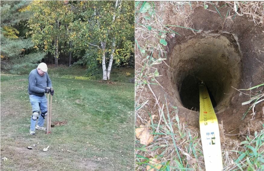
Preparing the base for the mast
The Yaesu 800DXA Rotator that will rotate the mast and antenna will be mounted to a steel pipe buried and cemented into the ground. The next step is to dig the hole. The maximum reach of this post hole digger is around three feet.
Next, place the pipe in the hole and make sure it is vertical.
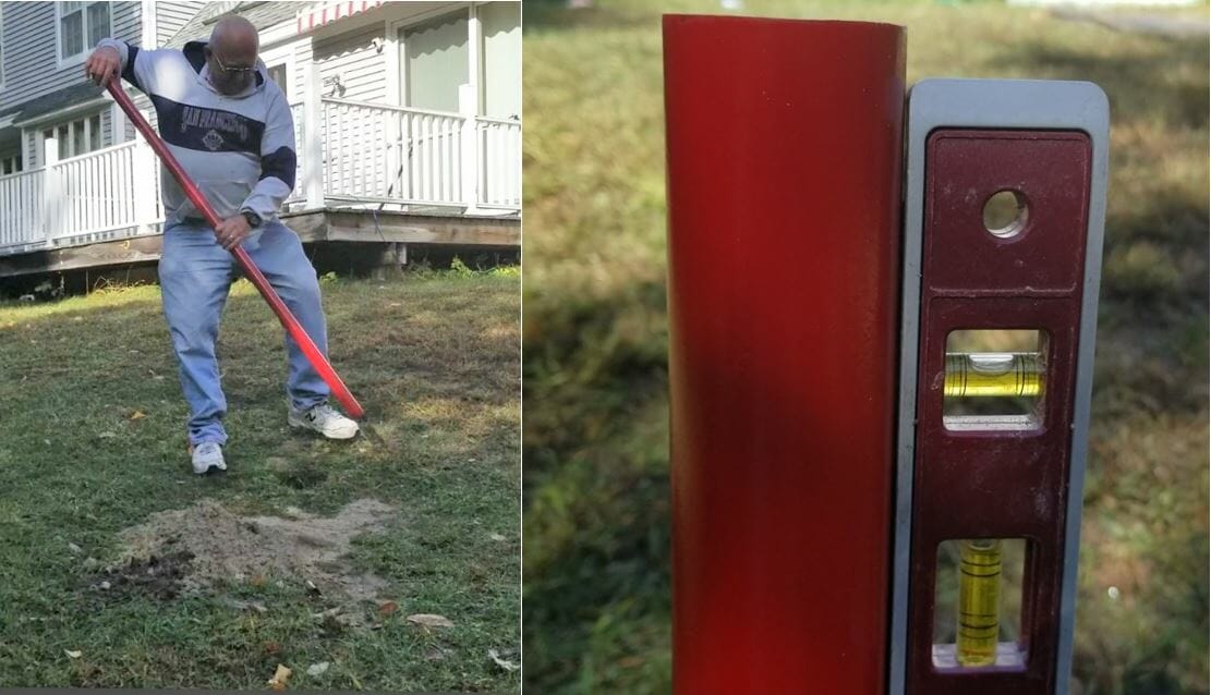
Add about 6 inches of gravel to the bottom of the hole to promote drainage, then add dry quick setting concrete to a few inches below the top of the hole. Slowly add water to the dry mix and give it time to soak in. One bag was sufficient.
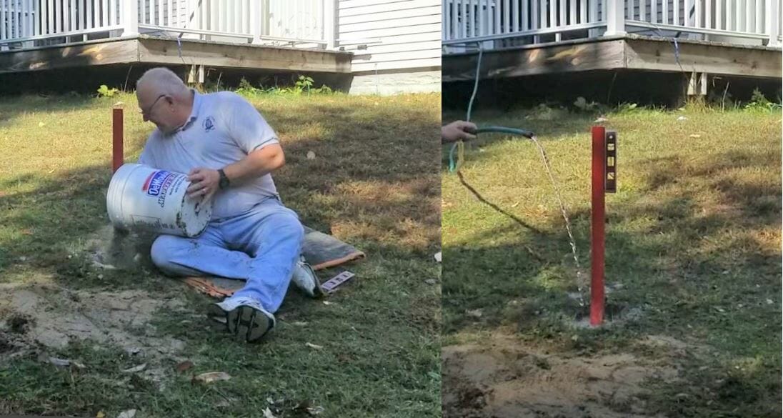
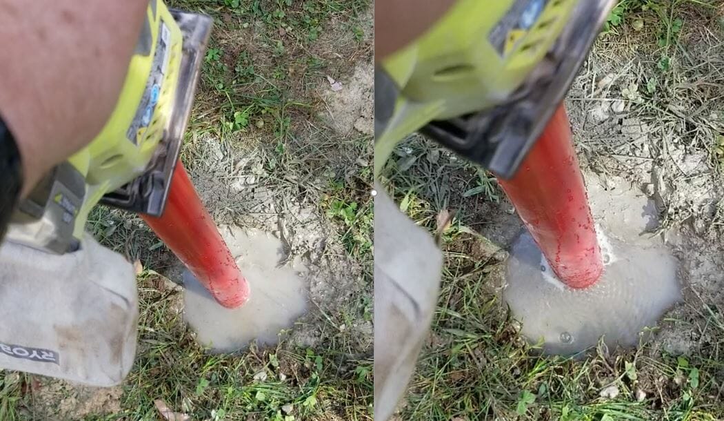
After adding water to the cement, I saw it was not draining very quickly. I had the inspiration to use my palm sander, without any sandpaper, to vibrate the pole. It worked great and you can see how the water level dropped and the bubbles coming out of it. I am confident this made the concrete stronger.
Read the Manual Before Antenna Assembly
While I wait for the concrete to cure properly, I will construct the antenna. The Spiderbeam antenna packs into a compact box. The mast is a Spiderbeam 14.5 Meter HD model and is rated for full height with this antenna. The 14.5 Meter HD telescoping mast has 9 sections. Each section is around 6 feet long. When fully extended it is 47 feet long. Assemble the antenna directly onto the topmost section of the mast.
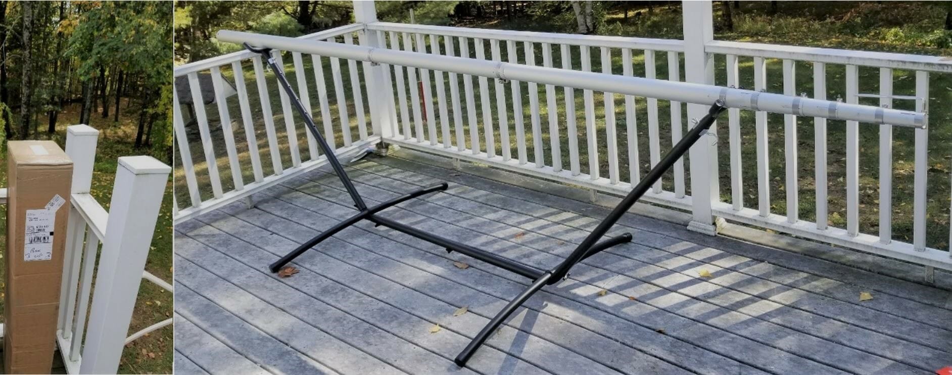
Spiderbeam includes a printed booklet with detailed assembly instructions and you can also download a PDF with the latest version of instructions from their web site. They will also provide plans to construct it yourself if desired. After assembling their kit I can say that building this from scratch is a challenging project. The components they provide are of high quality and worth the money. I highly advise everyone to read the assembly instructions over at least twice before beginning work. The manual includes instructions for the user who builds from scratch and also from the kit. It covers the portable as well as the HD versions of the antenna. Even after reading the instructions twice myself I still had to backtrack a few times to complete the assembly properly.
Beginning Antenna Assembly
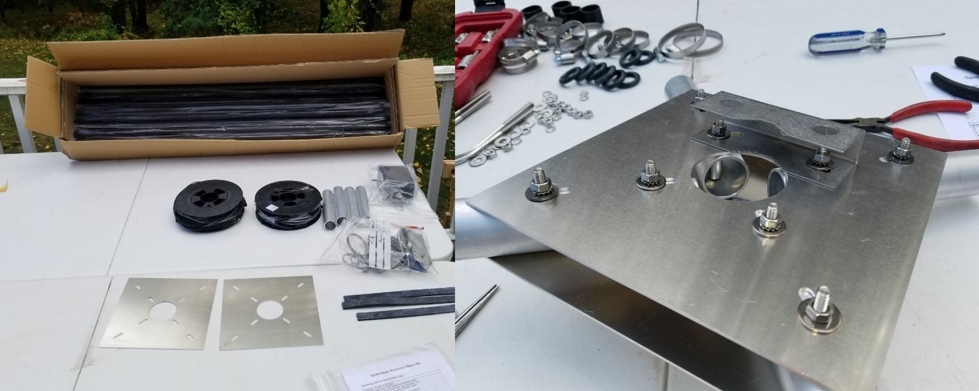
The box contains 20 fiberglass tube segments along with all the other parts required to assemble the antenna. I purchased the optional Kit Assembly Service from Spiderbeam where they manufacture the wire elements, guy lines, balun, etc. This is very worthwhile and quite a time saver. The two spools of wire shown above include all the reflectors, directors, and driven elements accurately measured. The wires on the spools are in the correct order of use. This makes it simple to access the next wire needed when assembling the antenna. The wires are accurately measured, but they are not precisely tuned. Do this once the antenna is fully assembled and off the ground a bit.
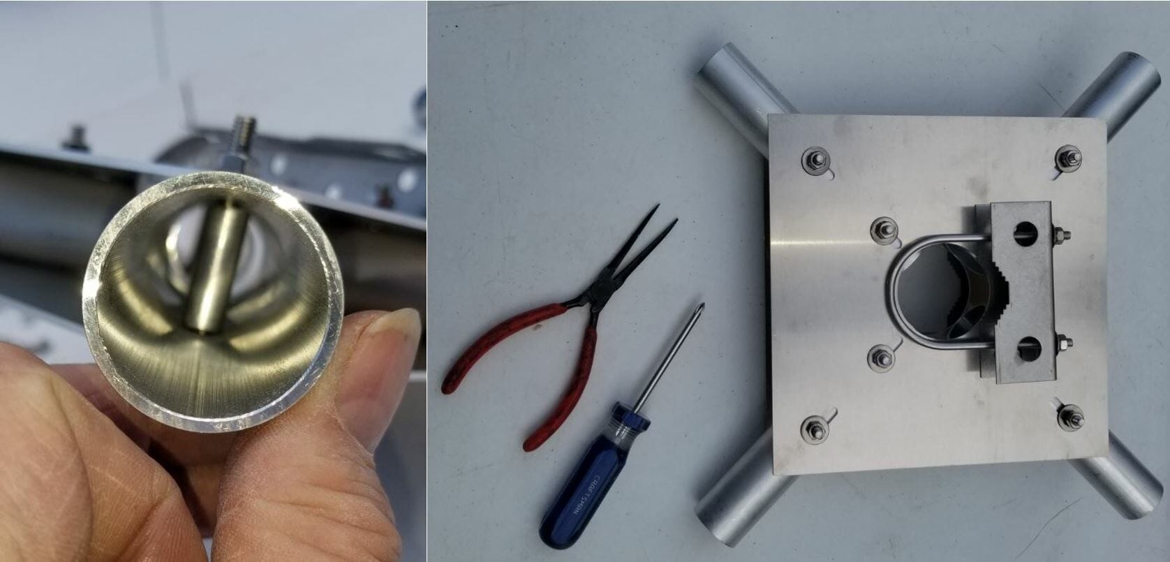
The pictures above show some detail of the Spiderbeam Center Joint. Where the bolts go through the tubes there is a sleeve to install in the tube to prevent it from collapsing when you tighten the bolts. It takes some finesse to align the parts. I used a very long nose needle nose pliers to hold the sleeve in the tube during assembly. It is even more tricky when attaching the brackets on the top and bottom of the hub as many pieces need to be stacked up and aligned before you can insert the bolt through the sleeve.
Installing the Spreaders
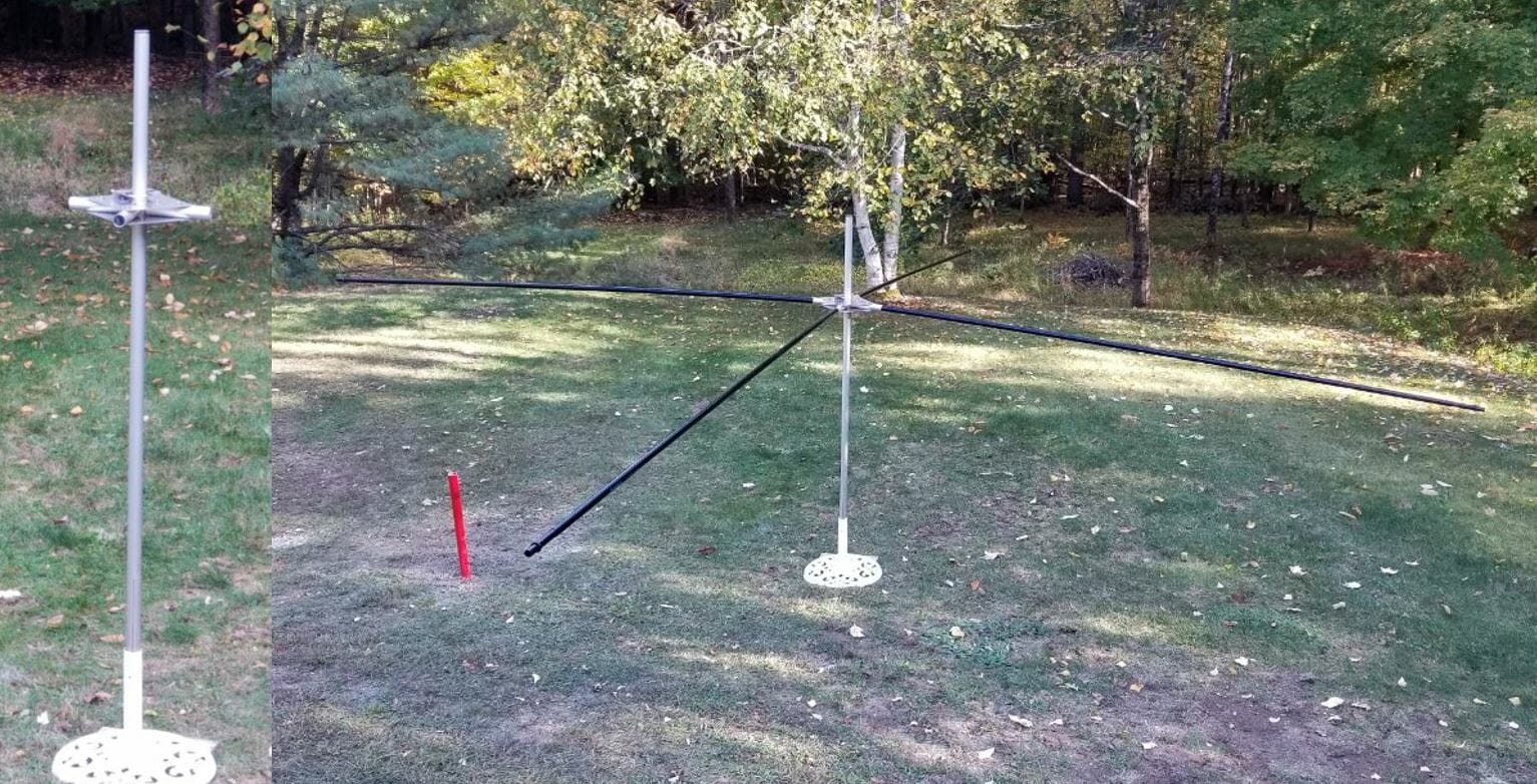
To aid in the assembly I placed the topmost section of the mast into a garden umbrella holder. Spiderbeam specifies that you install the hub 50cm from the top of the mast. I found this to be a bit short and will make an adjustment in the future to make it 65cm. This will give the top support guys more leverage for the spreaders. There are intermediate detailed steps as each component is installed. The instructions keep it on track.
Installing the Wires
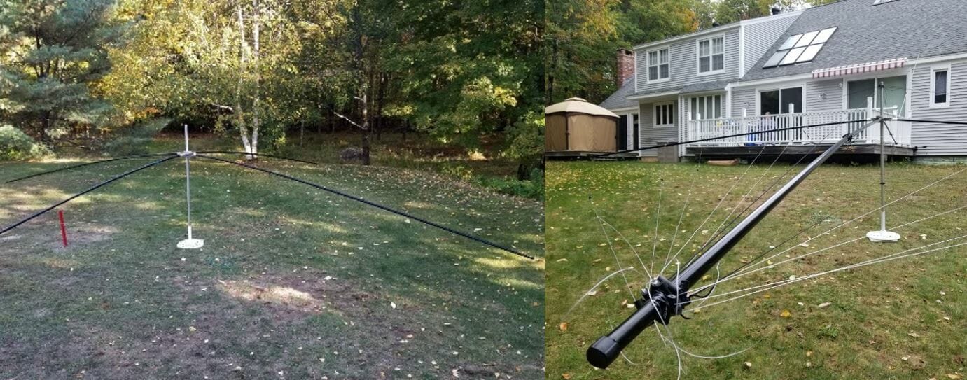
The next step is to add the Reflectors and Directors. I found it useful to have the antenna up high enough that I could easily duck under the wires as I put them on and adjust them.
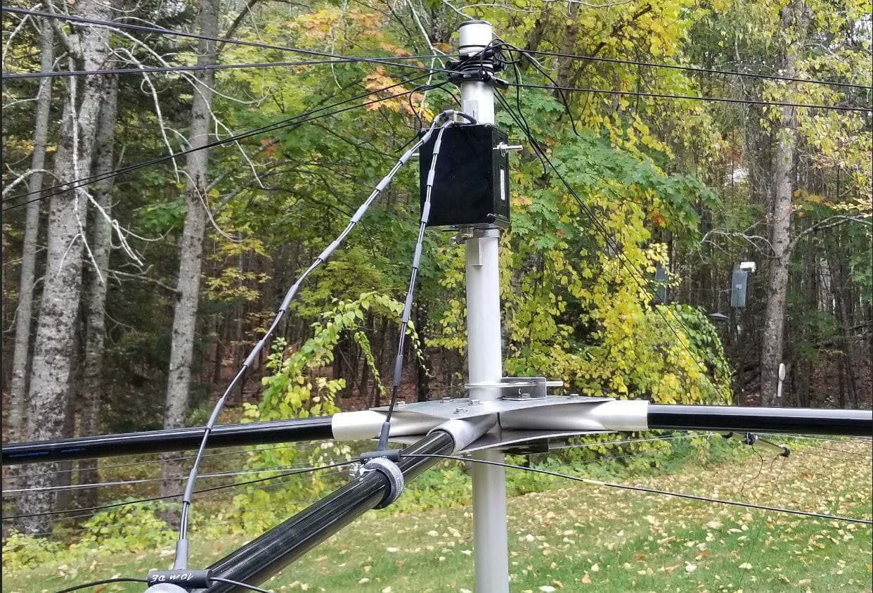
Before installing the driven elements install the balun on the mast. There is a terminal label for each driven element. Left and right sides are identified on each element and it is important to orient them correctly when connecting them to the balun. After this, install the wires in the order shown in the manual.
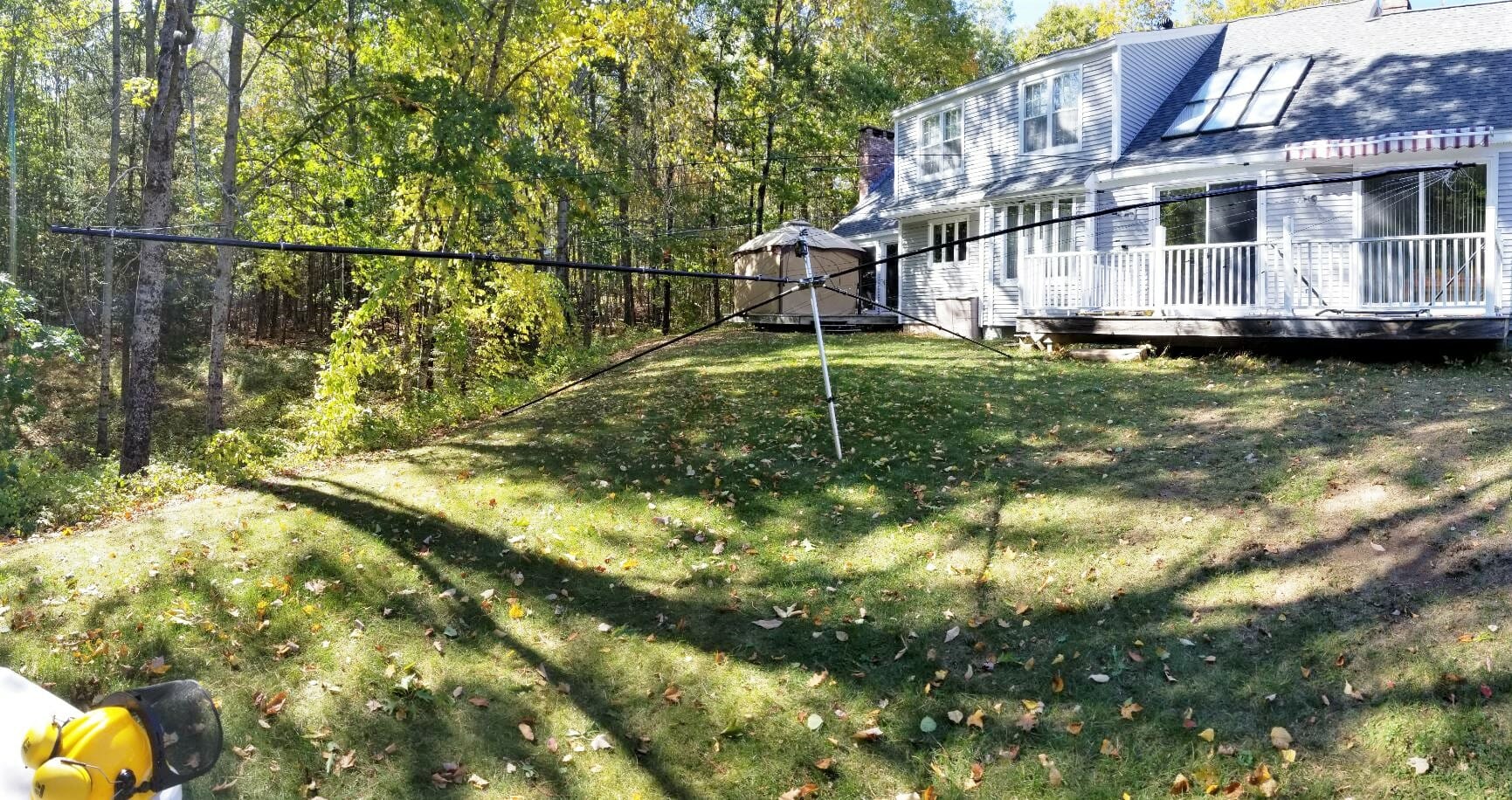
Finally, I picked up the completed antenna and moved it out of the way so I would have room to work on the next phase, raising the Spiderbeam. It weighs about 30 LBS. including the mast. It is certainly the largest single item I ever lifted and moved. There is lots of inertia to manage, but with care, I moved it easily. You can see how large the antenna footprint is with it on the ground. This is the end of Part 1. Part 2 will be coming soon.
Jon, AC1EV