Tag Archives: Antennas

WM0G Rain Gutter Antenna

Several years ago, I wrote an article on the use of the rain gutter on my Colorado home as my HF antenna. This was the antenna I was relegated to use for my HF operating due to the oppressive rules of the local Home Owners Association regarding external antennas. Although I did remind them at the time that it was illegal to ban small outdoor satellite dishes and Yagi’s for TV reception per the FCC, so they amended that clause in the HOA covenants, but still continued their ban on any outside ham antennas. I’ll not complain, as I knew what the HOA rules were when I got this house and accepted them as a challenge to my ingenuity.

Rain Gutter Antenna
Rain Gutter Antenna

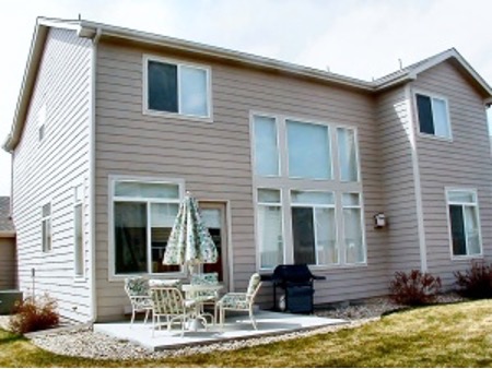
One day I was looking around to see what I could use to support a wire on the roof and got an idea to try to use the aluminum rain gutter on the east side of my house as my HF antenna instead. The gutter measured 25 feet vertically and then ran 35 feet horizontally for a total of 60 feet in overall length and resembled a ready-made inverted “L” or what is also known as a Marconi antenna configuration. That antenna needs a decent counterpoise to work correctly so I planted fifteen random length radials under the lawn. I then wired together the three aluminum window wells that were on that side of the house and added them to the planted radial wires. Additionally, I bolted together all of the aluminum lawn edging around my lawn and added a wire from that into the other counterpoise elements. According to the accepted theory, the more metal and wire you use in your radial system, the better. You might consider connecting to your radial system any nearby chain link fencing, metal lawn sprinkler piping, buried metal screening, water standpipes, underground water storage tanks, metal drainage culverts, railroad tracks, etc.

After the installation and in the initial trials, one of the drawbacks I noticed on the rain gutter antenna was that it was somewhat tricky to load on some of the bands using a conventional antenna trans-match. It was impossible to find a decent matching combination on 160 meters at all. Although, loading on the 80, 40, 30, 20, and 15 meters bands did not present as much of a problem and I could get an SWR match under 3:1 in a few small portions of those bands. Tuning on 10 meters was a bit tricky as well as finding any sort of decent match on 12 meters and 17 meters.

I looked at several possible solutions including one developed by my good ham friend, stealth antenna compatriot, DX’er, celebrated author, and renowned Physicist – Dr. Yardley Beers, WØJF (now SK) who volunteered to do all the complex mathematical calculations on my rain gutter antenna system. In a few days, he gave me a coil design that could be added to the feed point of the rain gutter in order for it to load on 160 meters. There was no doubt in my mind that his design would work.

Ultimately, though, I had decided on using a different approach. I had read a lot about the SGC-230 Smartuner™ Automatic Antenna Coupler in ham magazines and on the Internet. It seemed like a plausible solution to this problem IF it worked as advertised. The automatic antenna coupler is designed for use with end-fed unbalanced antennas such as whips and long wires. It can be configured to be used with dipoles and inverted vees as well. This automatically tunable antenna coupler is an ideal solution for this type of installation due to the fact that a rain gutter looks like a non-resonant end-fed unbalanced antenna.

What is the difference between an antenna coupler and an antenna tuner? According to the SGC manual, “antenna couplers” are placed at the antenna and match conditions of the antenna to the feed line in a very precise manner whereas, “antenna tuners” on the other hand, are generally located at the transmitter output at the transceiver end of the coaxial feed line. Furthermore, antenna tuners placed at the transmitter allow substantial losses in feed lines to be corrected at that point in order to “fool” a transmitter into working correctly. The losses are dissipated through heat or to ground. Conversely, a coupler installed at the antenna eliminates these losses by providing a proper match of the antenna at the feed point. The SGC-230 Smartuner™ is a true antenna “coupler”.

SGC-230 Smart Tuner
SGC-230 Smart Tuner

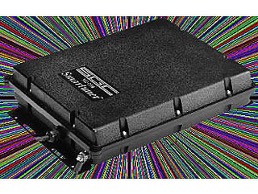
After purchasing the SGC-230 Smartuner™ from my local Denver HRO store I couldn’t wait to get it installed. Included within the formidable packaging of the box was an impressive and informative 81-page installation and operating manual that explained the coupler’s inner workings and it suggested various antenna applications for the SGC-230 with illustrations. Upon physical inspection of the unit, I was impressed by the ruggedness of the construction of the SGC-230. This hermetically-sealed antenna coupler was obviously meant to be installed outdoors and was even suitable for installation on shipboard. At a major military show,

I even saw one mounted on the side of an Army Humvee connected to their whip antenna! SGC builds other models of these types of antenna coupling devices but the SGC-230 Smartuner™ is rated at 200W input. I probably wouldn’t ever run more than 100 watts, but it is comforting to know that you are not running on the hairy edge of the limits of its power capabilities. I figured that the additional margin would translate into many extra years of trouble-free operation.

The feed to the rain gutter is barely visible in this photo as well as the braided connection to the radials.

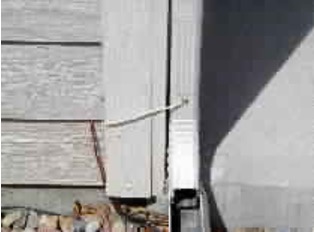
The installation was a snap. SGC gives you an additional quick installation guide for those of us that don’t like to read the whole manual. First, I mounted the antenna coupler as close as possible to the feed point of the rain gutter per the specification in the installation guide. This is because any portion of the feed wire that is connected to the SGC-230 becomes part of the overall length of the antenna too.  So, I mounted my unit on the inside wall of the foundation of the basement just above the wooden base plate and below the flooring. This location was just opposite the downspout of the rain gutter, which served as my antenna feed point on the outside. A short distance of 8 inches away. I drilled two holes just larger than the O.D. of the intended feed-thru wires through the 2×12 inch base above the concrete foundation and on through to the outer siding. Then I took apart a piece of RG-8X coax and separated the inner conductor from the braided shield. The inner conductor would serve nicely as the feed wire from the coupler to the downspout. You are cautioned in the instructions not to use coax to hook up these auto couplers on the antenna feed side. The now-separated braided shielding served as the hookup to the outside radial wires and was then connected to the ground lug provided on the SGC- 230. Now all that was left was to connect the RG-8X coax from my rig to the input of the cable harness provided with the SGC-230. There is a set of control wires and voltage wires included in this coaxial cable harness. The +12 VDC hot wire and ground went to my 12 VDC power supply. There are control signal leads that are also provided that are used for an indication of the coupler`s tuning. An LED “antenna tuned” indicator was connected between +12 VDC and the control signal wire. When the antenna coupler has found a match, the coupler drives the signal to ground on the control wire, which causes the LED to light. It provides a good visual indicator close to my operating position because I can’t hear the quiet auto coupler relays engaging from my operating position. The total time for installation, from getting the unit out of the box to starting the initial testing, was under an hour.

To me, the “proof is in the pudding” and my acceptance would be how well it performed in on the air tests. First, I tried to load up the antenna on all the bands from 10 through 80 meters. Wow! no problem whatsoever! All bands indicated a 1:1 SWR and the initial tuning time on each band was from 3 to 4 seconds for finding a match. The Smartuner™ automatically evaluates and switches 64 input and 32 output capacitance combinations plus 256 inductance combinations in a “pi” network which equals over a half-million matching combinations. Once it finds a match, the SGC-230 has 500 memories in which it stores the LC combination in its non-volatile computer memory so that the next time that you operate on that same frequency it tunes almost instantaneously, usually in less than 10 milliseconds. Now for the band that I hadn’t been able to get a match on before… 160 meters. I went down to the CW portion where I usually operate and it found a match within 4 seconds. Life is good again! I also did not notice any “hunting” by the SGC antenna coupler once it has been tuned to a frequency.

I decided I would wait until the evening to perform some on the air experiments with some people I knew. I checked into a WAS Net on 75 meters that I have been active on for over 20 years and knew most of the hams there. These unwitting participants in my on-air tests were giving me S7 to S9+ reports from New England to California and from British Columbia to Florida. I had not let on to anyone before the net that I had done anything to my antenna system and thought I’d gather a few willing souls after the net to give me some further signal reports.

I was getting reports of S6 in New England later on as the band seemed to be changing a little but I was still getting S9+ reports from the southern states and was still S7 into British Columbia and Washington State and S9 into California. Most of these good folks know that I am using a rain gutter for an antenna but some of them think I am kidding them about it and using something more formidable for an antenna and maybe even a linear! So, after telling everyone on the WAS net about my latest antenna configuration and new addition, I got a comment from a station in Arkansas who said, “If I could put a signal like that out from my rain gutter, I’d get rid of my dipole and my linear too!” He said that my signal had been over S9 all night at his QTH. The band conditions were decent this particular evening but the reports were consistently well above previously logged reports I’ve had with those very same stations in the past under similar band conditions without the coupler. The signal reports remained fairly constant, plus or minus band conditions over the years.

K5K Kingman Reef DXpedition QSL

Later that same week, I noticed on the DX-Cluster that the long-awaited K5K Kingman Reef DXpedition was up and running. This would be an ATNO (all-time new one) for me if I could get through the pileups. I knew that CW would be my best chance early on and I’d try for the SSB contacts later on during the DXpedition when the “big guns” had gotten their fill and their “feeding frenzy” was over. I caught K5K easily on 30 meters – no problem, as everyone on that band is fairly equal due to the power limitation. Later, I worked K5K on 15, 17, and 40 meters CW. I even got them on 40 meters SSB too! Finally, one evening I saw a spot for K5K on 160 meters. I hadn’t actually operated down here before with the rain gutter due to the problems I have previously noted. I heard him and set up split about 1.5 kHz up and slipped in my callsign fully preparing to be there for a while as his presence had attracted a fairly good pileup. He came back to me on my very first call! I was so shocked that I didn’t answer right away. I just kept staring at my radio – it was like having “buck fever” when you are out deer hunting. He sent my callsign again. I hurriedly snapped out of my trance and jumped onto my Vibroflex key and gave him the usual 5NN 5NN CO TU ES 73 DE WMØG. He acknowledged my reply and continued on to work the rest of the pileup. Not too bad! My very first 160 meters contact on the rain gutter was a rare DX station in a pileup. I was even more impressed now with my new antenna coupler. It had ‘played’ as advertised and had already justified its pricey self in my mind. I like to imagine that the other guys in that pileup thought that they had initially lost out to some “big gun” top band DX’er with his quarter wavelength high 160 meters 4-square vertical array and multi-KW amplifier — HI!

Since that time, I casually worked over 220 countries (all bands), and had enough confirmed QSO’s for WAS on 75 meters SSB. I even participated in the ARRL SSB Contest and managed to work 45 different countries in just 98 contacts, mostly on 20, 15, and 10 meters. These were accomplished in a little under three hours of actual operating time while being particular on who I called while “searching and pouncing”. While this is certainly not an impressive “run-rate” it is still is not a bad testimonial to the capabilities of the rain gutter antenna and SGC-230 automatic coupler combination. Even if one considers that most of the contest ops on the receiving end were using much more impressive antennas in order to hear me. Most stations I called were still coming back to me on my first or second call, except for a few of the rarer ones who had lots of QRM on their frequency.

I know now that when I install my next mobile HF radio installation, it too will have an SGC antenna coupler just ahead of the whip. Reports I’ve read on the resultant combination of the SGC series automatic antenna couplers used with plain steel whips have been very good from 160 meters on up. I also have read independent reviews that it works incredibly well with the equally pricey, but efficient, matching the SGC-303 9-foot tall mobile antenna. No, I don’t work for SGC, but I am a satisfied customer, and I don’t mind spreading the word about their quality products.

With regards to my experiences using a rain gutter for an antenna, I write this article in the fervent hope that some covenant-restricted or apartment dwelling ham, somewhere, will be inspired to replicate some form of stealthy antenna system as I, and many others, have done too. I would hope he or she would also then share their enjoyment of being on the HF bands with a respectable signal, despite the covenanted restrictions and physical obstacles around them.

This article is certainly not technical in its content, nor was it meant to be so. It is, however, testimony that one need not have ideal antenna conditions in order to operate effectively on the HF bands. Many books have been written on the subject of stealth amateur radio operation and all of them offer some very sound advice regarding the subject of stealth antennas. I suggest that if you have a desire to run a stealthy ham station you consult these books first. Also, go to the SGC web page and download one of their online manuals for their antenna auto couplers where you will find even more ideas and solutions. In the back of their manual under “Smartuner™ Installations & Applications,” you will see my rain gutter antenna article as well. Also, Steve Nichols, GØKYA published my article in the RSGB. I’m always interested in anyone who has been inspired to try this combination and hear about their success.

Jack, WM0G

Introduction to HFTA – High Frequency Terrain Assessment and more…

What is HFTA

HFTA stands for High-Frequency Terrain Assessment.  Some documentation refers to it as High-Frequency Terrain Analysis.

HFTA is a software tool that generates the vertical radiation pattern of horizontally polarized antennas taking into account the profile of the surrounding terrain. The irregularity of local terrain has a profound effect on vertical radiation patterns. Note that HFTA does not compute radiation patterns for vertically polarized antenna radiation.

Azimuthal Maps

Request Azimuthal Map

HFTA provides performance information for your antenna taking account of the terrain profile in a particular direction.  Do you know what is out there in any direction?  Standard Mercator maps show a representation of the world, but do not provide important information that is of use to Hams.  There is a website that will create a map with your location at the center of it.  It is free and all you need to know to use it is your grid square info.  The more info you have the more accurate the map is.

Check out   https://ns6t.net/azimuth/azimuth.html

Tewksbury Azimuthal map

Above is a map for Tewksbury, MA

Yaesu Rotator Controller

You can put the map on your rotator controller to show where it is pointing.  Some computer-based rotator control programs can also use the image.

Take-off Angles

ARRL Take Off Angles

Why use HFTA

Use HFTA for planning an HF station scientifically.  It can assist with determining the optimal antenna location and height. HFTA takes ground elevation data, frequency, and the height of the antenna to calculate the take-off angle in a specified direction. It is particularly useful for Hams interested in DX and contesting. Many of us use some type of propagation prediction tool to give us an idea of what bands may be open at a given time and to a specific location.  Once the terrain profile and antenna information are configured the results can be used to provide a tool for propagation prediction that is custom tailored to your precise situation.  This is very helpful when formulating strategies for contesting or hunting down rare DX.  Terrain around your antenna up to 10,000 feet has a significant impact on your signal.

HFTA Models
HFTA Models

Typical questions that HFTA can answer

  • How high should my antenna be?
  • Is it worth spending more money on a taller tower?
  • My mast is up 35 feet. Is it worth it to extend it to 45 feet?
  • Why can’t my antenna hear signals from ??
  • About to by a new house? Is the house location well suited for Ham Radio?

How does it work

1. Generate terrain profile data files.  These are created using digital terrain data available from various online databases. There are a few additional programs that can be used to create these files and the HFTA instructions cover the required steps in detail.

2. Choose the type of antenna and the number and heights of antennas in a stack.

3. Select the type of antenna to be used.

4. Select an Elevation-Statistics file for your targeted receiving area.  This file will include your station location (receiving area) and the area from which you will be receiving signals.

The software includes files with statistics that were computed for all the times over the 11-year solar cycle when each band was open.  The Antenna Book’s data contains files for all regions of the USA to Europe (EU), the Far East (JA), South America (SA), South Asia (AS), Southern Africa (AF), and the South Pacific (OC), plus data files for a wide variety of other transmitting sites throughout the world. You choose the general area where your transmitter is located during initial installation of the HFTA program.

How to get HFTA

How to get HFTA
How to get HFTA

HFTA is included in the ARRL Antenna Book (currently 24th Edition).  It is part of the package that includes the book when you get it for download from the ARRL.  It was also included in a CD that came with the physical book.  The e-book or Kindle is available from different sources.  To be sure you get the software files associated with the book I suggest ordering it directly from the ARRL.  Here is a link:  http://www.arrl.org/shop/ARRL-Antenna-Book-eBook-Windows-Version/

K6TU.NET

K6TU.NET
K6TU.NET

The website https://www.k6tu.net/ is an excellent resource in combination with the HFTA software and offers many tools and resources beyond those that support HFTA.

Users need to register for free to use the tools and there is also a subscription service which offers more tools that go beyond the scope of HFTA available.  To create HFTA Terrain Profiles, this website makes it very easy and offers very accurate data for stations located in the USA.

K6TU.NET provides a framework of simple to use forms to build propagation predictions or Terrain profile requests. Use the Resource menu at the top of the page to access guides, FAQs and background information.  Use the Getting Started page to start with a tutorial which will guide you through the steps to create your first prediction.

Generating an accurate terrain profile

K6TU.NET now has the capability to generate a set of profile files for your location by simply filling in a form and submitting the request. Much like generating a Propagation Prediction, the site captures the information necessary to fulfill the request and then generates the results in the background. Once the results are available, an email is sent to you with a link to the results.

Generating a Terrain Profile Request is very simple and starts by selecting Terrain Profile from the New menu at the top of the page when you are logged in as a registered user. You do NOT need to be a subscriber to K6TU.NET to access this service – it is freely available to anyone with an activated account.

When the request is completed, the site creates a Terrain Profile Result which has a link to the ZIP file containing the terrain profile files (360 of them, one for each degree of azimuth) together with an explanation of the source of the terrain data for this profile.

Terrain Data
Terrain Data

The screenshot above shows the 360 files for the terrain data for my QTH in Tewksbury, MA  I have another folder with the terrain data for my NH QTH as well.

HFTASweep

HFTASweep is a program “wrapper” for the ARRL HF Terrain Analysis program (HFTA). HFTASweep runs HFTA 90 times programmatically to model your HORIZONTAL polarized antenna over the actual terrain around your location. The program captures the results for each azimuth direction (4 different azimuth angles at a time) and at the end, builds a VOACAP type 13 antenna model as a file called antenna.13. You can upload type 13 antenna files to K6TU.NET and use them in the different prediction options by creating an Advanced Station Configuration from the New option under the Navigation menu.  Once you have the type 13 antenna file you can use it to create custom tailored propagation forecasts.  Here are a few examples:

HFTASweep
HFTASweep

This is 20 meters in May.  There is one chart per hour.

Custom Tailored Propagation Forecasts

One Hour Forecast
One Hour Forecast

Here is a close-up of one hour on 20 meters.

Contest Strategy

Contest Strategy
Contest Strategy

Another feature is to prepare multiple band reports to use for formulating contest strategy. Here is an example I created for my NH QTH for 13 Colonies back in July. There are very good instructions and examples on the K6TU web site. It is worth checking out.

How to use HFTA

Blank HFTA and Terrain Files

1. Launch the program

2. Select the terrain files you will use for this assessment by clicking in the box.  In this example we will examine performance for 50 degrees, which is towards Europe.  This Terrain File is for my MA QTH

HFTA Antenna Type
HFTA Antenna Type

3. Click in the Ant. Type box to select the antenna type from a pull-down list.  Enter the antenna height in the appropriate box.  You can stack antennas up to 4 high!

4. Repeat for other antennas, locations, and heights you wish to compare.  In this example I will add a 3 element yagi at 34 feet at my NH QTH (just select the Terrain Profile from that location) and a 3 element yagi at 45 feet from the NH QTH.

Add Elevation File
Add Elevation File

5. Enter the Frequency

6. Select an Elevation file.  These are included with the HFTA software.  They are the files derived from the 11-year statistical data mentioned above. This example is for Boston to Europe.

7. Check off the boxes for terrain for each antenna selected and HFTA will generate a profile for that compass heading.

Terrain Profile
Terrain Profile

8. The Options button lets you configure units of measurement, Diffraction on/off, and Soil Conductivity (among other things).  I have Diffraction turned on since I am around 3 miles from a ridge that is around 200 feet above my antenna. The chart makes it look like I am pointing into the hill, but it actually calculates out to be only 0.76 degrees up from my antenna.  I believe my soil in NH is “Good Soil” but I selected Average Soil to create a conservative assessment.

Options
Options
Ready to Compute
Ready to Compute

9. Click the Compute button to generate the chart.

My Results with HFTA

The Output Graph can be resized.  Here are my results for the three antenna configurations pointing to Europe:

My Results
My Results

The Purple bars show the take-off angle plotted against the percent of time that signals arrive at that angle.  This data is what is in the .prn files that you enter in the Elevation File field.  Each antenna profile’s performance is represented by the colored line on the chart.

There are some very interesting things that show up on this chart:

1. The Spiderbeam at 33 feet has better performance at low angles than at 45 feet.  Also, where the higher configuration is better, it is not a meaningful difference.

2. Both the Spiderbeam and the Hexbeam are adequate for coverage to Europe.

3. At this azimuth (50 deg) for some take-off angles the Spiderbeam has more than a 10 dBi advantage over the Hexbeam!  This is before any radio or amp is added to the calculation.

Figure of Merit

Figure of Merit
Figure of Merit

HFTA uses these elevation statistics, which indicate what percent of the time a signal arrives at a given elevation angle, and compares this info to your elevation plot, generating a relative performance rating called Figure of Merit, expressed in dB.

The software produces a “figure of merit” which is each antenna’s merit based on gain at takeoff angles where, statistically, the most prevalent signals can be expected. If you have great gain at takeoff angles where most of the time no signals are arriving, the FOM is low.  When comparing different antenna configurations, the FOM can be used to identify which has an advantage. For the Spiderbeam used in my Europe example, the FOM is the same for 33 feet and 45 feet.  The effort and risk to elevate the antenna does not appear worthwhile in this case.

Real World Example

Recently, I noticed a station from Kenya spotted on the cluster.  I took a few minutes and was able to make a call successfully to 5Z4BU.  I don’t often hear Kenya on the radio, so I ran an assessment using 77 degrees and the Africa Elevation file.  Here are the results:

Real World Example
Real World Example

In this case the Spiderbeam at 45 feet would have an advantage, but the antenna at 33 feet was still capable of receiving signals from any likely take-off angles.  The FOM for the 45-foot antenna was 1.2 higher than the 33-foot antenna.  The Hexbeam in MA may have been able to make the call, but there was a pileup and the additional gain from the Spiderbeam really helped.  I was able to make contact in 4 tries.

Australia and New Zealand

260 Degrees AZ Map
260 Degrees AZ Map

Here are two more examples to review.  First, we’ll look at Australia and New Zealand.  I’ll point my antenna at 260 degrees, which splits the difference between them.

Here is the terrain profile compared with the path covered on the map.

Lake Terrain Profile
Australia and New Zealand

The chart above shows that although New Zealand is around 9,000 miles away, it is not difficult to make contacts there as there are many take off angles that can give successful results.  You can select in the chart to capture a close-up of details.

Australia and NZ Close-up

The chart shows that the Spiderbeam at 45 feet will receive signals well at 1 degree and it looks like it will also at the 34-foot height.  The Hexbeam will likely miss signals at 1 degree but should handle 2 degrees fine.  New Zealand was one of my first Pacific DX QSOs and done with an OCFD and 100 watts.

Japan

Next, we can check out Japan, which is at 335 degrees.  We’ll review the steps again:

Japan
Japan

1.Select the Terrain files from each location for 335 degrees

2.Confirm Antenna type and heights are set properly.

3.Select the Elevation file

4.Click Compute!

Japan Chart
Japan Chart

This chart has lots of useful information.  Unfortunately, it does not indicate that I will have a high probability of success contacting Japan.  According to the chart, 20% of signals from Japan will come in around 1 degree and 15% at 2 degrees.  Both antennas will fail at this angle.  The Spiderbeam will have success from 3 degrees and higher.  It is interesting to note that the Hexbeam will perform better at 6-degree take-off angle.  Japan is only 6,700 miles away, but you can see it is way more difficult to reach than New Zealand.

Conclusion

  • This has been a simple introduction to HFTA. There are many documents and videos available that discuss the features of the program and strategies for using it.
  • How well an antenna “plays” depends on take-off angle to the target area, antenna height and local terrain
  • Lower is sometimes better.
  • More than one antenna per band will help your overall signal presence.
  • Design your antenna farm to cover all angles. If you can’t, choose what is important to you.
  • It is easier to make changes in the design stage of your antenna project. Time spent with this assessment tool can save big dollars and yield a better installation than trial and error.
  • The ARRL Antenna Book is a terrific resource. This presentation was based on only a tiny fraction of what the book covers. It makes a great gift, too!

Helpful Links

The ARRL Antenna Book for Radio Communications 24th Edition https://www.arrl.org/arrl-antenna-book

K6TU.NET | Propagation as a service

Practical Notes on Terrain Assessment (What I Have Learned in the Last Dozen Years) (seapac.org)

take-off angles Archives – KB6NU’s Ham Radio Blog

INSTALLATION (orcadxcc.org)

HFTA and your station (qsl.net) – great presentation info

December 08, 1997 by N6BV (arrl.org) – instructions

Takeoff Angles & HF Terrain Analysis (HFTA) — Presented by Kevan Nason N4XL – YouTube

Jon, AC1EV

Plans for Field Day 2021

We are holding an in-person Field Day operation at Keyes Memorial Park in Milford, NH. Here’s some more on our plans for Field Day 2021.

Stations and Antennas for Field Day 2021

We will be a 4A Station with the following Station available for members to use:

  • 20m HF Station (All Mode, can do SSB Phone, CW, or FT8/FT4 Digital)
  • 40m HF Station (All Mode, can do SSB Phone, CW, or FT8/FT4 Digital)
  • 10m/15m/80 HF Station (All Mode, can do SSB Phone, CW, or FT8/FT4 Digital)
  • 6m VHF Station (All Mode, can do SSB Phone, CW, or FT8/FT4 Digital)
  • Computer Controlled 2m/70cm Satellite Ground Station (Can do SSB Phone and CW)

We will have a Tower up with a Triband Yagi and Wire Antennas to Cover 80m – 10m. We will have a 6m LFA Yagi up for the Magic Band. Finally, we will have a Computer-Controlled portable satellite station with Yagis for 2m and 70cm.

You can see a prediction of the Satellite Passes during Field Day here.

Station setup will take place on Friday, June 25th with on-site activities beginning at 11 am.

We will hold a training session on our Stations and other Field Day fun on Saturday, June 26th starting at 12:30 pm. Training will cover:

  • Operating FT8 Digital and Using the 6m Station
  • Operating Using the Satellite Ground Station
  • Fox Hunting

Field Day Operations will begin at 2 pm on Saturday, June 26th, and go for 24-hours ending at 2 pm on Sunday, June 27th. We will take down our station beginning at 2 pm on Sunday.

We will be holding a Message Passing activity on Saturday afternoon at 3:30 pm. This is a great activity for Technicians – bring your HT and learn how to pass emergency message traffic at Field Day. Contact Aron at [email protected] for more information and to sign up.

Sign-Up To Operate!

Members can sign-up to operate in our Field Day forum.

Field Day Coaches

Field Day at the Nashua Area Radio Society is all about learning and trying new things. We encourage you to sign-up to operate our stations and to learn about modes and bands you may not have experience with. In addition to our planned training, we will have Field Day Coaches available to help you get started and learn to use our Station, and have fun operating.

Field Day Tech Night

We have held two Tech Night sessions to provide training on how to operate at Field Day. Members can view the videos and training presentations for these sessions on our Tech Night Page.

Visitors and the Public are Welcome

If you’d like to learn more about Amateur Radio, we’d like to invite you to visit us at Keyes Memorial Park during Field Day. Noon into the evening on Saturday, June 26th, and Sunday morning, June 27th, up until 2 pm in the afternoon would be a great time to stop by. We’ll be happy to show you around our site, answer your questions, and even get you on the air a bit if you’d like. Also, if you have an HT, bring it and you can hunt our Foxes (hidden radio transmitters).

Logistics for Field Day

We will be operating in the Open-Air Pavillion at Keyes Memorial Park. This will provide shelter should we have any rain. The Pavillion is one-air and this will facilitate safe social distancing and an outdoor environment.

We encourage everyone to get vaccinated for COVID-19 if possible before Field Day. Our site is set up to facilitate social distancing and we will have masks and sanitization supplies available onsite for those who need them.

Several members have graciously volunteered to handle Take Out food runs during Field Day operations. We will also have water and light snacks available.

If you have any questions about Field Day, please post them as part of this thread or email us at [email protected]. We hope that you’ll join us for Field Day!

The NARS Field Day Team

Radio Amateurs Developing Skills Worldwide