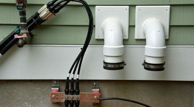
We recently completed the finishing touches on our new VHF and Satellite Tower. The first step was to install a second set of entry conduits into our shack and a new ground block for our satellite antennas…
Our Tower is finally complete! We’ve added an additional entry into our shack for coax and control cables and we’ve installed 7/8″ hardline coax cables to reduce losses in our 6m, 2m, 70cm, and 23 cm feedlines. You can see some photos and details of this part of our project via the link above.
We are working on upgrading our Flex-6700 SDR based Remote Gateway to include Satellite operation. Stay tuned for an article on this part of our project.
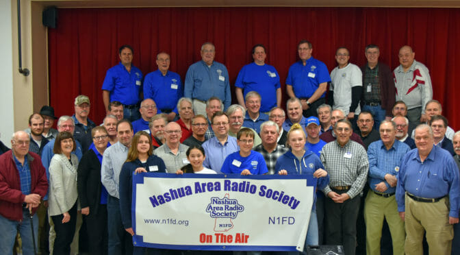
Quite a few Nashua Area Radio Society members are headed for the Dayton Hamvention® this week. The theme of Hamvention 2019 is “Mentoring the Next Generation”. We will be receiving some important recognition for our work to bring new Hams into the Amateur Radio Service, for our Amateur Radio related STEM learning programs in local schools, and for our many Ham Mentoring projects. We will be recognized as the Dayton Hamvention 2019 Club of the Year. We will also be sharing The Nashua Area Radio Society Story as a forum presentation at Dayton.
The Nashua Area Radio Society Story (click to view)
We are also being recognized by the ARRL as a Spotlight Club for our Mentoring work. The ARRL has dedicated their “ARRL Spotlight on Radio Clubs and Mentoring” forum on Friday, May 17th at 11:50 am in Forum Room 3 to us so that we can share The Nashua Area Radio Society Story including ideas and programs that have worked well for us. You can view a copy of the presentation that we’ll be sharing by clicking on the image above. The presentation contains links to the embedded videos so you can enjoy those as well.
I want to express my deepest appreciation and thanks to all of the Nashua Area Radio Society members have contributed so much to our many projects, programs, and activities. Without all of you, we would not have been able to do what we have done to help others and to forward the Amateur Radio Service.
We hope that our readers who will be attending the Dayton Hamvention this year will join us for our Forum Presentation on Friday and will also stop by and see our display in the ARRL Booth at Dayton.
We’ll be sharing highlights from Dayton 2019 in our Forums as we go and Scott, NE1RD has time planned for us to share our Dayton experience at an upcoming meeting when we return.
In the first RockMite article, I described the receiver of the radio. This article will describe the user interface for the RockMite. The term “user interface” might sound a little fanciful for a radio with almost no controls, but there is plenty to discuss. We should begin with the portion of the schematic dedicated to this function.
A portion of the schematic for the CPU and I/O functions
At the center of the schematic is a PIC processor from MicroChip corporation. These are small 8-bit computers that have dedicated I/O onboard. They are simple to program and are very inexpensive, key features for a radio that must cost under $50. Two of the input lines for the processor (pins 6 and 7) go to a 3.5mm stereo connector for iambic paddle input. Pin 6 connects to the “dash” or “dah” line, and pin 7 connected to the “dot” or “dit” line of the paddle. One of the functions of this PIC microprocessor is to provide the radio with an iambic keyer function.
The other user input is a single button. This button serves multiple purposes. A press of less than a quarter second tells the processor to “shift” the radio’s frequency. More on this in a bit. A longer press (greater than a quarter second) puts the keyer into “speed adjustment mode” that monitors the paddle inputs. Tapping or holding the “dit” side increases keyer speed; tapping or holding the “dah” side decreases keyer speed. Do neither for a second-and-a-half and the processor reverts back to standard iambic keyer mode.
The “shift” mode is the more interesting effects from a button press. The RockMite is actually able to operate on TWO frequencies, not just one. There is a special circuit in with the crystal controlled oscillator that causes this frequency shift. That will be discussed in the next RockMite article. All we need to know for now is that the “shift” line comes out of pin 3 and controls a 2N7000 transistor switch.
The other two outputs of the microprocessor are to the sidetone and the transmit/receive (T/R) switch. The sidetone is the sound you hear when keying. That’s the audio feedback on your paddle operation. The RockMite sends a square wave from this pin to the audio amplifier described in last month’s article. The sound of a square wave in your ears is harsh, and there are a number of mods available to clean this up.
The T/R line controls the mode of the radio. Is it in receive mode or transmit mode? This will be discussed in the article that deals with the transmitter.
This was a brief article but we’re left with two interesting threads to pull on: radio’s oscillator (and shift function), and the radio’s transmitter (and the T/R switch). We’ll start with the oscillator next time.
We use cookies to ensure that we give you the best experience on our website. If you continue to use this site we will assume that you are happy with it.