A Broadcast Interference (BCI) Notch Filter for General Coverage Receivers

General coverage short-wave receivers may lack preselection against strong AM broadcast stations, and these broadcast stations may overload the receivers. SDR receivers, particularly the USB type[1], that plug into your computer are examples of this receiver type.

When I was designing my 10-band QRP transceiver, I wanted to incorporate an AM notch filter into the receiver for general coverage. In this mode of operation, the bandpass and lowpass filters are bypassed leaving the front end of the receiver wide open.

Since there are no FM broadcast transmitters nearby, I chose to include a notch filter for AM only because the receiver gain in my QRP transceiver from 88 to 108 MHz is greatly attenuated.

Rather than design and build a suitable notch filter, I looked for a suitable commercial off-the-shelf  (COTS) product that I could package into what I wanted.  The solution was the Nooelec Flamingo+ AM – High Attenuation Broadcast AM Bandstop (Notch) Filter[2].

My transceiver is based upon the N3FJZ software and hardware architecture [3], and Rick’s software architecture provides for general coverage whenever the receiver is tuned to other than one of the 10 designated ham bands. Thus, under these conditions, all of the filters in the transceiver are switched to bypass mode. I made use of this feature to incorporate the Nooelec Flamingo+ AM Notch filter in the bypass path.

Should I decide to incorporate an FM notch filter into the design in the future, the Nooelec Flamingo+ AM notch filter is easily disconnected from the printed circuit board carrier, and it may be replaced with a Nooelec Flamingo+ FM – High Attenuation Broadcast FM Bandstop Filter [4].

The schematic of what was built is shown in Figure 1. Optically coupled, 2-channel Arduino relays[5] are employed. When a bypass command is asserted in software, the receiver RF is routed around the bandpass and lowpass filters in the transceiver when it is in receive mode, only, i.e., the bypass does not function when the transceiver is in transmit mode.

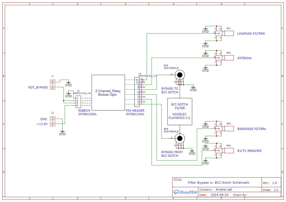
Figure 1. Filter Bypass With BCI Notch Schematic. When the software command is asserted to place the transceiver in bypass mode, the relay modules will bypass the bandpass and lowpass filters in the receive path and insert the Nooelec Flamingo+ AM – High Attenuation Broadcast AM Bandstop (Notch) Filter. Since the AM BCI notch filter is connected to the PCB with right angle SMA connectors, it may be replaced by an FM BCI notch filter, as desired. Please click on the figure to enlarge it.

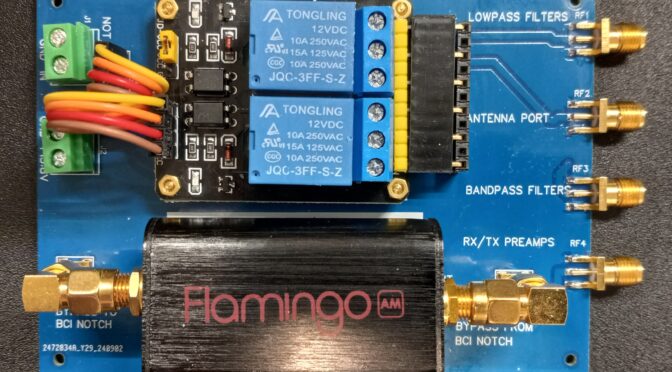
A printed circuit board, Figure 2, was designed as a carrier for the optically coupled relays and AM BCI notch filter. Pin headers are used for all connections to the 2-channel relay modules. Dupont[6] wires provide easy interconnects for power and logic inputs while pin headers are used for relay connections into and out of the printed circuit board. Dupont wires may be homebrewed with suitable component parts and a crimping tool, or they may be purchased at predetermined lengths.

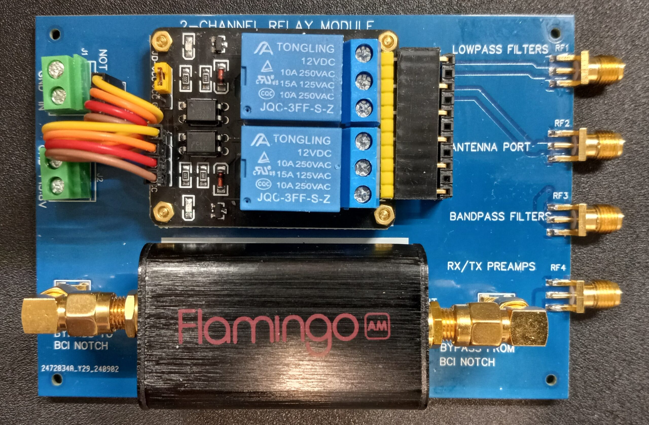
Figure 2. As-Built AM BCI Bypass Printed Circuit Board. The AM notch filter may be replaced by an FM notch filter of similar form-factor by disconnecting the right-angle SMA connectors. Please click on the figure to enlarge it.

Finally, the response of the Nooelec Flamingo+ BCI Notch was measured on a spectrum analyzer with integral tracking generator. The result obtained is shown in Figure 3. The measured notch depth is close to 70 dB over most of the AM broadcast band. This result compares favorably with the plot provided by Nooelec[7] in Figure 4.

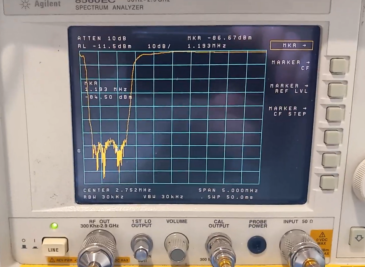
Figure 3. Measured Nooelec Flamingo+ AM BCI Notch Depth. The performance of the AM BCI Notch printed circuit board was measured on a spectrum analyzer with integral tracking generator. The notch depth is approaches 70 dB over most of the AM band. Please click on the figure to enlarge it.

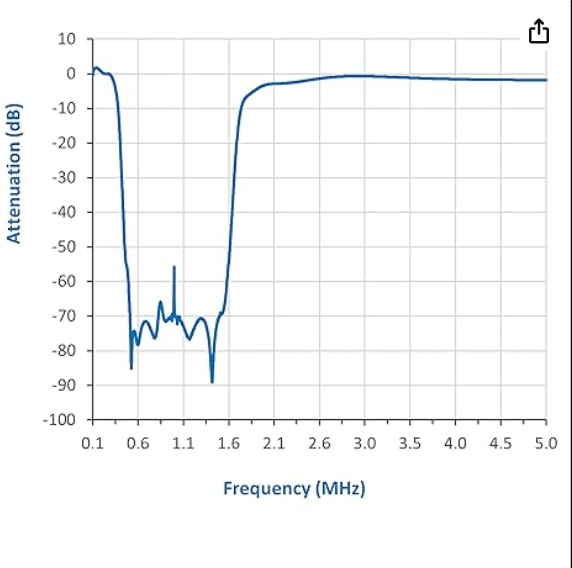
Figure 4. Nooelec Data. The plot found in the Nooelec data sheet compares favorably  with the measured data of Figure 3. Reproduced with permission from Nooelec. Please click on the figure to enlarge it.

Anyone wishing to duplicate this printed circuit board may contact me for a Gerber file. I will not be offering any printed circuit boards.

References:

1. https://www.nooelec.com/store/sdr/sdr-bundles/hf-bundles.html

2. https://www.nooelec.com/store/sdr/sdr-addons/flamingo-plus-am.html

3. http://www.remmepark.com/circuit6040/MAX-SSB/MAX-SSB.html#110

4. https://www.nooelec.com/store/sdr/sdr-addons/flamingo-plus-fm.html

5.https://www.amazon.com/gp/product/B081MVCS8F/ref=ppx_yo_dt_b_search_asin_title?ie=UTF8&psc=1

6. https://www.amazon.com/TOAPPNER-Multicolored-Breadboard-Arduino-Raspberry/dp/B089FZ79CS/ref=sr_1_2_sspa?crid=IB4C4C33XMM4&dib=eyJ2IjoiMSJ9.tjHxIQLJsk16_0YVtUGN6Tqnr8euWNsWVjpSaq5RQkYtxZ9Cezy7x5qOhagKvYtMzwlO3bKCBbaL1aW0gvt6neKoy9ihFziKKV1XaMgGsZAE8xRYaSTrpxQdRvB0pAUE20gJVd3C2KcNPIu-KcdICH9n984YMZgPEz0KU8pLTtGa-RcD9BD6ef2DqvC9xEyQTaj2b0LmfNg1lNr1V_BlptXMnJAI1jqwkYqPQCB5h5I.fVWAD3xtI6a-TS73_L9fQ9c26h3fo70muKyIhPmYqA4&dib_tag=se&keywords=dupont%2Bwires&qid=1732556600&sprefix=dupont%2Bwires%2Caps%2C99&sr=8-2-spons&sp_csd=d2lkZ2V0TmFtZT1zcF9hdGY&th=1

7. https://www.nooelec.com/store/sdr/sdr-addons/flamingo-plus-am.html. Op cit.


Memorable Conditions on the 6M Band – An F2 Opening

6M F2 Opening

We have recently seen some amazing conditions on the 6M band from here in New England, USA. For about five days, we saw daily F2 openings to Europe and the Western USA. During this time, we were able to work in Alaska and numerous new grid squares in the Northwestern USA, Canada, Central and South … Continue reading →

Source: Memorable Conditions on 6m – Our HAM Station

Anita and I have been enjoying operating on the 6m band during November 2024. We’ve seen some of the best conditions we’ve yet experienced on the Magic Band. We’ve been working on many new Grid Squares and DXCCs on 6m. You can see what we worked via the link above. You can also learn more about our 6m antenna system here.

Want to learn more about how to get on the 6m Band? Check out our January 2023 Tech Night on 6m Antennas.

Fred, AB1OC

A Simple Set of QRP Calibration Mismatches That You Can Build

I enjoy homebrewing, and when it was time to calibrate the Stockton Bridge for measuring forward and reflected power in my QRP rig, I realized that I didn’t have a set of mismatches that could be used for that purpose. A set of mismatches is also useful for checking an SWR meter, or a nanoVNA. There are off-the-shelf mismatches that you can buy to test your nano, but they do not provide the power handling capability that this design does.

If you would like to get started with PCB design, this might be a perfect project to begin with. I am not endorsing any particular PCB design tool that you might find online, but I have found that EasyEDA is easy to learn.

The mismatches that I describe here can be used for QRP. All resistors in the design are 51-ohms and 2 Watts. Since we are not using 50-ohm resistors, this will result in a small error. Also, the layout is distributed (spread out), and this will result in a bit of extra capacitive reactance for the larger mismatches. SMA connectors were chosen because all of the RF interconnections within my QRP rig consist of RG316 terminated with SMA connectors.

Figure 1 is the schematic of what was built. It seemed pretty easy to construct the mismatches from a single value of resistor, but there is nothing to stop you from building mismatches from one or two parallel values of different resistors. What I have here seemed like a good idea because it made calculations simpler, and it resulted in power-handling capability large enough for any QRP project that I envisioned. Values of 3.0:1, 2.5:1, 2.0:1, 1.5:1 and 1.0:1 were chosen as data points for the Stockton Bridge that I was calibrating. For continuous operation at 5W, a cooling fan is recommended, particularly for the 1.0:1 load bank as it has the fewest number of resistors.

Figure 1. A Simple Set of Mismatches. Use of a single resistor value, 51-ohms and 2 Watts throughout, makes construction easy and economical. Use of series and parallel combinations result in higher power dissipations. Please click on the figure to enlarge it.

Figure 2 shows the virtual 3-D layout as provided by the EasyEDA PCB layout tool. The tool shows you what you are going to get once the PCB is assembled. The EasyEDA library is extensive, and it provides additional capability to import manufacturer’s symbols and footprints not already in the library. Although this set of mismatches was built as a PCB, there is nothing to stop you from building the same design on a piece of copper-clad perforated board.

Figure 2. Calibration Mismatches 3-D View. EasyEDA provides a 3-D viewer so that you can see what the final product will look like before the PCB is fabricated and before the PCB is populated. The mismatch values are shown near the SMA connectors. Please click on the figure to enlarge it.

Figure 3 shows the shows the final product after PCB fabrication and population. It closely matches what is shown in Figure 2.

Figure 3. As-Built Calibration Mismatches. The actual PCB closely resembles the 3-D model shown in Figure 2. The overall dimensions of the completed board are 6.50” x 3.60” including the connectors. Please click on the figure to enlarge it.

S11 values for the mismatches were measured from 1.8 to 29.7 MHz and stored on an old MFJ-226 Graphical Analyzer. The values were converted to rectangular form in Excel spreadsheets to facilitate calculations. Smith Charts were also plotted. In order to make this article more concise, the Smith Charts are provided in the Appendix that follows.

If you would like the S11 data in the form of Excel, please contact me. The spreadsheets contain all of the formulas required to convert S11 magnitude and angle to other useful forms including S11 rectangular, impedance rectangular, impedance polar, VSWR and return loss.

If you would like the Gerber file for PCB fabrication, you may also contact me.  I will not be providing any bare boards, although you may wish to pool a PCB order to distribute the shipping costs among a few hams. For the JLCPCB supplier, the minimum number of boards is 5.

Appendix A. Smith Charts

Figure A-1. Smith Chart 1.0:1 Mismatch.

Figure A-2. Smith Chart 1.5:1 Mismatch.

Figure A-3. Smith Chart 2.0:1 Mismatch.

Figure A-4. Smith Chart 2.5:1 Mismatch.

Figure A-5. Smith Chart 3.0:1 Mismatch.

Radio Amateurs Developing Skills Worldwide