DIY 6m Moxon Antenna

6m Moxon antenna
6m Moxon based on a plan by Bruce Walker N3JO

The ARRL book Magic Band Antennas for Ham Radio by Bruce Walker N3JO has the plans for a 6m Moxon Antenna that I found interesting because, instead of wire or tubing, it uses 3/4″x1/8″ aluminum stock available in hardware stores in 4′ or 8′ lengths.  No bending, just drilling!  I’ve worked on it bit by bit over the last few months or so, and the CQ VHF contest this weekend gave me the extra push I needed to get it up into the air!

I got 8′ sections of the aluminum stock, but I cut the center of the parasitic element (the longest piece) into 2 pieces of less than 4′ each, in case I want to pack the antenna into a car.

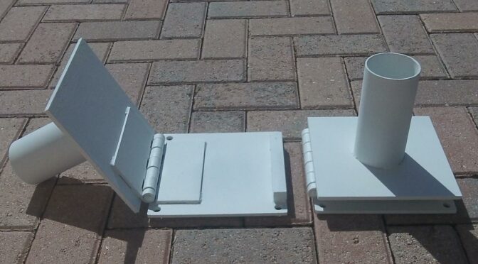
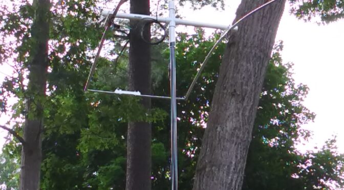
The boom is PVC pipe, and for the spacers between the active element and the parasitic element, I used a 1-1/2″x3/4″ vinyl substitute for wood used for trim, which is also available in hardware stores.  I cut it down to 3/4″ wide strips for the insulators between the ends of the elements.  Unlike the book, I used the full width to attach the elements to the boom so that the U-bolts could be attached beside, instead of under and through, the elements.  (It was not at all clear to me from the book’s drawing — no photographs — how the parasitic element was attached to the boom given the bolt positions as drawn.  Also, I may have misunderstood if the author meant 1″ ID or 1″ OD pipe; since it is Pipe, I assumed it was ID.)

I made a coil balun as described in the book, and the UHF connector is mounted on a right-angle piece of plastic cut from an inexpensive outlet box which is a trick suggested in the book.

I put Noalox on the stainless steel nuts and bolts to prevent them from “welding” themselves together and also to protect the aluminum from the stainless steel.

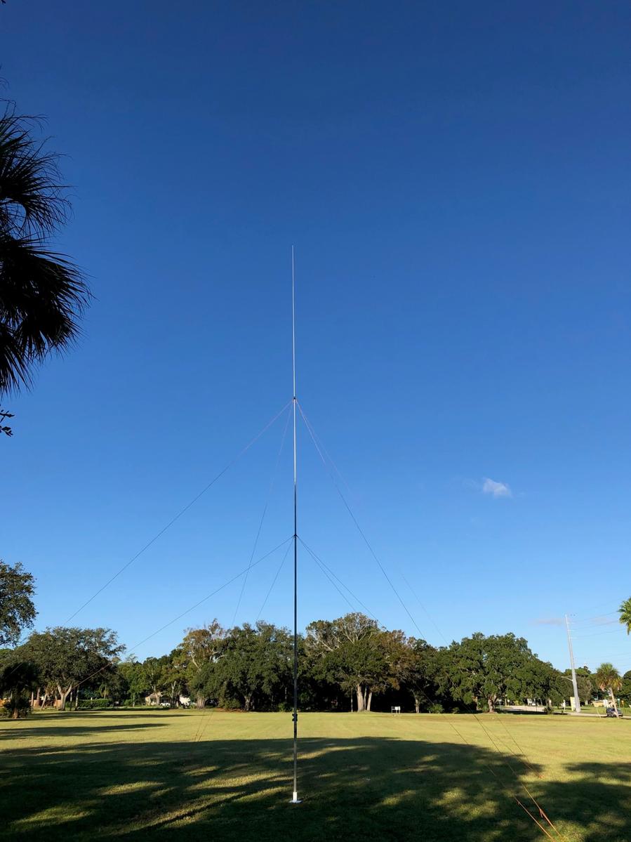
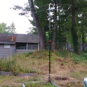
I changed my ideas on how to get it up into the air a couple of times, and today I finally just went and got an MFJ-1911 lightweight fiberglass mast and a set of MFJ-2830X guy rings at our local “candy store.”  (I wish there were a ring in the set with an even larger center hole.)  I did not extend it to the full 20′ (yet, anyway) because I was concerned that the antenna was too heavy, so it is only about 14′ up in the air now.

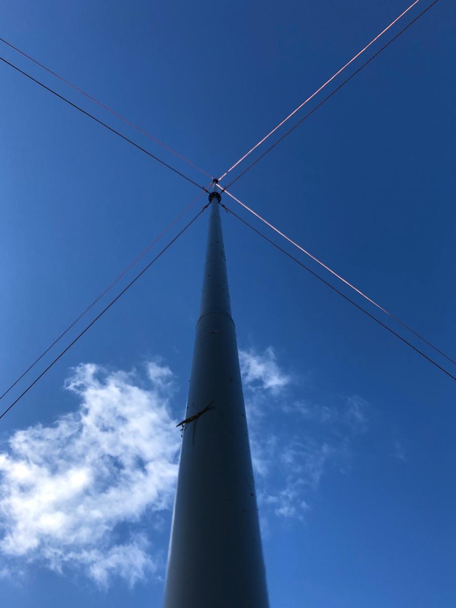
I used hose clamps (threaded through a water drain tube, so the clamps don’t cut into the mast) above each exposed joint in the mast to give added protection against the “twist lock” mast unlocking and collapsing into itself.  I put another one around the base with loops of paracord through it that I can hold down with tent stakes, in addition to putting the base of the mast against one of the raised garden beds to keep it from slipping.  (I’m sorry, I don’t recall which video blogging ham I learned those hose clamp tricks from.)

6m Moxon antenna
6m Moxon based on a plan by Bruce Walker N3JO before it was raised up

The 6m Moxon Antenna ended up being tilted slightly (actually, rotated around to be almost upside-down!), but I’ve got some U-bolt saddles on order to fix that.  (They’ll be the two pieces of metal besides the aluminum elements that aren’t stainless steel.  Unfortunately, I used a smaller size U-bolt than what seems to be the “standard” for antenna masts of about 2″ inside diameter for the U-bolts.)  I made an extension that screws in above the vertical piece of PVC pipe through the boom so that I could add support ropes for the insulators far out from the center of the antenna, but I haven’t put it on yet to save weight.  (I may replace the mast with a heavier-weight product from MFJ to allow this and to raise it higher.)

6m Moxon antenna
6m Moxon based on a plan by Bruce Walker N3JO

As you can see below, the minimum SWR is 1.0 at about 52,140 MHz, not the point in the 6m band where I would like it for FT8, but at least it is in the lower half of the band.  (I haven’t thought about how to tune it or if I need to.  But I do know that I want to replace the thin coax feeding the antenna now with LMR-400.)

SWR curve hitting 1.0 at about 52,140 MHz

With much-appreciated help from my XYL Merle W1MSI, I was able to get the DIY 6m Moxon Antenna up late this afternoon and try it out before the band closed for the day.  The “magic band” did what it does, and I was able to make 27 QSOs on VHF with FT8, from my shack in FN42 (southern New Hampshire) to as far as EL98 (Florida) and  EN52 (Wisconsin).  So I think the antenna is working pretty well.  It is the first beam antenna at my shack.

For a while there, I was happily collecting DXCCs and US states on HF with SSB, but then I discovered FT8, and after that FT4, and now I’ve got grid squares to collect on VHF — so I have even more paper to chase!

Aron, W1AKI

Control Your Rig Remotely With This USB-Controlled Power Station

Introduction

Remote station operation has become more popular now that several rig manufacturers offer accessories to enable the radio amateur to do so. However, there is usually a large expense associated with acquiring these accessories. For some, it may not be cost-effective to own them for occasional use. In this article, we describe a solution for remote operation from another room of your home, your yard, or while on travel. It is also convenient for controlling on/off functions in the shack with the click of the mouse. The solution revolves around a Velleman relay card that can control a number of relays from a computer desktop.

The Power Station

This article describes a USB-controlled AC power strip, Figure 1, that was built around the Velleman K8090 8-Channel Relay Board in kit-form [1]. Varistors were added to the board as a recommended option [2]. The board can also be purchased fully assembled [3].

Figure 1. USB Controlled Power Strip. Each 15A duplex outlet is under USB control. There are just enough contacts on the barrier strip for 8 relays, neutrals, and grounds.

The PC communicates to the board via USB. A free, desktop, graphical user interface (GUI) is provided by Velleman for use as test software, or you may opt to purchase an application such as N-Button Lite [4].

Some type of rig interface is required to control your rig and audio from a PC. You may use the interface in your rig if it has one, or buy or build one of your own.

In order to log onto your computer, see your desktop remotely and hear rig audio, some kind of conferencing software is required. I use TeamViewer [5] to see my desktop and hear computer audio remotely.

Cautionary Notes

You will be dealing with AC line voltage in this project. Keep the clear polycarbonate cover on the enclosure while AC power is applied. Since the Velleman card operates on 12 VDC and control is over USB, all testing can be completed prior to plugging the AC line cord into the wall socket.

The FCC requires some means to disable the transmitter within 3-minutes if something goes wrong during remote operation. Velleman makes a WMT1206 Universal Timer Module with USB Interface [6] that should prove useful for this application. Its relay can handle 8A of AC. There are also similar USB timer modules available on eBay. It’s also a good idea to have the ability to reboot your computer remotely. The exact details of how to implement this FCC requirement are left to the reader but there are plenty of suggestions to be found online.

Kit Construction

An experienced kit builder can assemble and test the board in an afternoon. The added varistors are specified at 125J, 300VAC, 385VDC, and 4500A clamping peak current [7]. If these are not readily available, there are equivalents. A suggestion was made to thicken the circuit board traces that must handle the 16A relay current with additional solder. I didn’t care for this approach and opted to solder bus wire onto these traces, instead. You might find it ludicrous to solder #14 AWG buss wire onto the board, so your other option is to derate the relay capabilities to what the conductors can safely handle since the PCB traces have not been rated. For example, the ampacity of #20 AWG buss wire is at least 5A (11A at 75°C) [8], and that will be good for 575W. None of the circuits that I run from this PCB require anywhere near 575W.  Take care not to damage the PCB traces while soldering. Excessive heat will lift the PCB traces.

Housing, Connectors, and AC Outlets

There are 8 duplex outlets in this project – each one under separate relay control. Each outlet has been wired with #14 AWG. Each relay is rated at 16A, resistive load (see the previous section for derating). The duplex outlets have been spaced far apart so that a variety of line cords and wall adapters will fit without interference. The control board is housed in a Bud Industries PN-1340-C polycarbonate enclosure [9] with a clear cover (not affixed), Figure 2. The clear cover provides visibility for the status lights on the PCB. Bud Industries also manufactures an internal aluminum panel, PNX-91440 [10], upon which the PCB and barrier strip have been mounted. Take care in locating connectors on the housing or the PCB will not fit. The PCB is fastened to the aluminum panel with 4-40 hex standoffs. The Bud Industries enclosure is fitted with 1/2-inch male terminal adapters [11] at either end. DC power for the relays enters the enclosure at the top left through a 2.1mm panel mount connector [12]. The relay power required is 12VDC at 400mA. A 12 VDC wall adapter with a 2.1mm plug can provide this voltage. AC power enters the housing through a cable gland at the lower left. Switchcraft makes the USB connector at the lower right. It converts USB A inside the enclosure to USB B on the outside. The connector was purchased from Newark [13]. The short USB jumper patch cord was purchased on Amazon [14]. A step drill [15] is the most effective way to bore the large holes in a polycarbonate or ABS case without cracking it.

Remote Control

Figure 2. Interior View of Control Board Enclosure. Eight 16A relays are visible. There’s not much space to spare. Take care in wiring the AC connections and in locating the connectors on the housing or the PCB will not fit.

Software Apps

The test software that is supplied by Velleman for the circuit card is adequate, or N-Button Lite [16] may be purchased Figure 3. A screenshot of the lower right corner of the monitor shows the buttons for N-Button Lite. The green buttons indicate that four of the eight relays are active. If you purchase the Bud enclosure with a clear polycarbonate cover as I did, you will be able to see all eight red indicator lights on the Velleman board, one for each relay. They will light when a relay becomes active.

Remote Control

Figure 3. Screenshot of PC desktop. N-Button Lite controls each of 8 relays.

References

References
[1] https://www.jameco.com/z/K8090-Velleman-8-Channel-USB-Relay-Card-Kit_2123952.html
[2] https://www.velleman.eu/products/spareparts/?code=vdr300
[3] https://www.amazon.com/Velleman-VM8090-8-Channel-Relay-Card/dp/B00CPCQ88Y
[4] https://www.serialporttool.com/GK/n-button-lite/
[5] https://www.teamviewer.com/en-us/?utm_source=google&utm_medium=cpc&utm_campaign=us|b|pr|19|jul|Brand-TeamViewer-Exact|free|t0|0|dl|g&utm_content=TeamViewer_Exact&utm_term=teamviewer&gclid=Cj0KCQjw5ZSWBhCVARIsALERCvzZflNoCfAiFgi9STEIDiJkCtRuazuukru
[6] https://whadda.com/product/universal-timer-module-with-usb-interface-wmt206/
[7] Velleman, op. cit. https://www.velleman.eu/products/spareparts/?code=vdr300
[8] https://en.wikipedia.org/wiki/American_wire_gauge
[9] https://www.budind.com/product/nema-ip-rated-boxes/pn-series-nema-box/ip65-nema-4x-box-with-clear-cover-pn-1340-c/ – group=series-products&external_dimension
[10] https://www.budind.com/accessories/aluminum-internal-panel-pnx-91440/
[11]https://www.homedepot.com/p/1-2-in-Male-Terminal-Adapter-R5140103/202043509
[12] https://www.amazon.com/2-1mm-DC-Power-Jack-Chassis/dp/B073PKZPQ7
[13] https://www.newark.com/switchcraft-conxall/ehusbbabxpkg/usb-adapter-type-b-rcpt-a-rcpt/dp/08N9043?gclid=Cj0KCQjw5ZSWBhCVARIsALERCvycmWj-i38ykHaPrlbG8Eb-uxCyxcpZzdNWmZ0r7Z2iV9zgd7CpVKAaAh5KEALw_wcB&mckv=_dc|pcrid||plid||kword||match||slid||product|
[14] https://www.amazon.com/inch-USB-2-0-Male-Cable/dp/B079ZP65SN?th=1
[15] https://www.homedepot.com/s/step%2520drill?NCNI-5
[16] Relay Pros, op. cit. https://www.serialporttool.com/GK/n-button-lite/

Tilt-Over Bases for Antenna Masts That You Can Build

Introduction

Most of us have installed temporary antenna masts and have looked for a way to raise, lower and guy the masts while working alone. This was the case when I wanted to raise three masts for temporary antenna testing. When I couldn’t find any tilt-over bases that were sturdy, I decided to design and build some of my own from readily available materials.

I wanted mast bases that were rugged and heavy, not thin and flimsy. I discovered that mild steel [1] with its high carbon content is easy to weld, so I settled on that material. I also found a source for mild steel hinges [2]. They were perfect matches for mild steel plate. (In case you prefer aluminum, heliarc welding has become routine. It all depends upon what the welder quotes for a price and how heavy you want the bases to be.)

A sketch of what was built appears in Figure 1. All of the dimensions are based upon available materials. The only cutting required was to fabricate a steel shim [3]. When the tilt-over base is in its upright position, this shim, which is the same thickness as the hinges, maintains the spacing between the steel plates.

tilt-over bases

Figure 1. Design Sketch. The small holes in the left base plate accommodate 3/8” spikes (see text). The steel tube is welded to the rear side of the right top plate (see text).

A local welder assembled three tilt-over base mounts from supplied 8″ x 8″ x 1/4″ mild steel plate, 3″ OD 11 gauge steel tube, 6″ x 6″ steel hinges, and 3/4″ x 3/4″ x 6″ steel bar stock. The steel plate, hinges and bar stock were ordered from Amazon, while the tubing [4] was ordered from Coremark. The ID of the base tube is 2.75″ (70mm), 11ga. This is a loose fit for the cap at the bottom of most fiberglass masts. I used felt blankets [5] as shims for a tighter fit and to protect the masts. The base mounts are anchored to the ground with 3/8″ x 12″ galvanized spikes [6]. Four ½” holes drilled in the bottom plate for this purpose are visible. The spikes prevent the bases from sliding while the masts are being raised and lowered.

Once welded, the welding flux should be removed. Since high carbon steel will rust, the welded assemblies were cleaned and prepped with phosphoric acid [7] and steel wool before priming with spray metal primer [8]. The primed bases were spray-painted [9]. The finished product is shown in Figure 2.

tilt-over bases

Figure 2. Tilt-Over Bases. These tilt-over mast bases are sturdy and stable when anchored to the ground with 3/8″ x 12” galvanized spikes. The tilt-over feature makes it easy to raise and lower portable telescoping and non-telescoping masts while working alone.

A typical installation is shown in Figure 3. The 33’ (10m) masts shown were guyed at two levels with guy rings. Four Dacron paracord guy ropes were used on each guy ring. Fluorescent orange paracords were used for enhanced visibility. Temporary ground anchoring is accomplished with polycarbonate Orange Screws [10] as shown in Figure 4. Taut-line hitches are used to tighten the guying ropes – a useful knot to remember.

The mast is raised with two lower guy ropes in place. The ropes are adjusted to hold the mast a few degrees past vertical until the final two lower guy ropes are placed. Finally, the upper four guy ropes are placed.

Figure 3. Typical Installation. Guying is performed at two levels. The mast is raised while working alone with two lower guy ropes in place. The ropes are adjusted to hold the mast a few degrees past vertical until the final two lower guy ropes are placed. Finally, the upper four guy ropes are set. A post level, visible on the mast, is used to true it up. Photo courtesy of N4UM.

Figure 4. Guy view. The masts are guyed at two levels. Eight Dacron paracord ropes are used. The paracords are fastened to the guy rings with snap hooks. Tensioning is adjusted with taut-line hitches. Photo courtesy of N4UM.

Figure 5. Orange Screw Ground Anchors. The guy ropes are adjusted with taut-line hitches. During antenna range testing, the Orange Screws were set in sandy soil. Three masts remained standing during two weeks of rain and stiff winds.

Figure 6. Antenna Range with 3 Tilt-Over Bases in Use. An antenna range was constructed with three fiberglass masts and tilt-over bases. The dimensions of the range are as pictured. This 140’ range was left unattended during 2 weeks of Florida spring wind and rain. Note that paracord back-guys were employed at the very tops of the north and south masts to relieve the lateral loading due to the weight of the wire. Without back-guying, the top sections of the telescoping masts are apt to snap off.

References*

[1]https://www.amazon.com/s?k=8+x+8+x+1%2F4+steel+plate&crid=188CJTXB7VM3W&sprefix=8+x+8+x+1%2F4+steel+plate%2Caps%2C585&ref=nb_sb_noss_2
[2]https://www.amazon.com/Hinge-Weld-Heavy-Metal-Doors/dp/B0821HQQSJ/ref=sr_1_5?crid=3UEBPDTTXJFF8&keywords=6%22%2Bsteel%2Bhinges&qid=1656544819&sprefix=6%2Bsteel%2Bi%2Caps%2C107&sr=8-5&th=1
[3]https://www.amazon.com/1018-Drawn-Steel-Square-Stock/dp/B09GY7MQ2V/ref=sr_1_3?crid=3DB0BOW75U320&keywords=3%2F4+steel+bar+stock&qid=1656544926&sprefix=3%2F4+steel+bar%2Caps%2C192&sr=8-3
[4]https://www.coremarkmetals.com/electric-welded-erw-round-steel-tube
[5]https://www.homedepot.com/p/Everbilt-2-in-x-4-in-Heavy-Duty-Self-Adhesive-Beige-Felt-Blanket-3-Pack-804614/306229475?
[6]https://www.lowes.com/pd/Grip-Rite-12-in-x-3-8-in-Spike/3610436
[7]https://www.homedepot.com/p/Klean-Strip-1-Gal-Concrete-Etch-Metal-Prep-and-Rust-Inhibitor-GKPA30220/100406369
[8]https://www.homedepot.com/p/Rust-Oleum-Stops-Rust-12-oz-Flat-White-Clean-Metal-Primer-Spray-7780830/100143442
[9]https://www.homedepot.com/p/Rust-Oleum-Stops-Rust-12-oz-Protective-Enamel-Semi-Gloss-White-Spray-Paint-7797830/205585926
[10]https://www.sportsmans.com/camping-gear-supplies/tents-shelters/tent-accessories/orange-screw-small-ground-anchor-4-pack/p/1531885?channel=shopping&gclid=Cj0KCQjw8O-VBhCpARIsACMvVLMO-RmVGrVvtXURmIiQcQRsAo_r91rbskWRWtAzqqAUniop6Wnm5QYaAutREALw_wcB
[11]https://www.amazon.com/Orange-Screw-Ultimate-Ground-Anchor/dp/B01D3UIA5A/ref=asc_df_B01D3UIA5A/?tag=hyprod-20&linkCode=df0&hvadid=167119746601&hvpos=&hvnetw=g&hvrand=17637355299886752168&hvpone=&hvptwo=&hvqmt=&hvdev=c&hvdvcmdl=&hvlocint=&hvlocphy=9002271&hvtargid=pla-307839372670&psc=1

*The references cite readily available sources of supply. You may be able to find lower prices for materials or substitutions elsewhere.

Radio Amateurs Developing Skills Worldwide