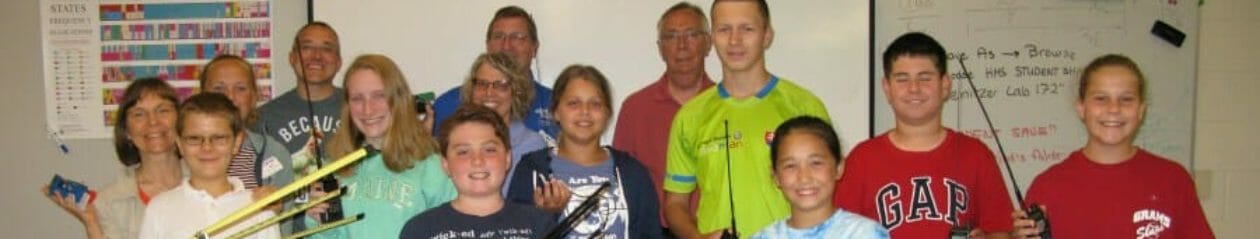

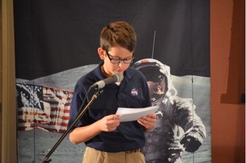
A select group of youths at The BIG E in West Springfield will soon have a once-in-a-lifetime opportunity to chat with an astronaut aboard the International Space Station (ISS) orbiting 260 miles above the earth.
Along with them, hundreds of Big E attendees and spectators will be able to watch the live contact as it occurs from The BIG E Arena. The exact time and date of the contact will be posted soon at key locations throughout The BIG E, or visit the Amateur radio booth (#103) inside Door 6 of the Better Living Center.
BIG NEWS from The BIG E! Hams who show up on the day of The BIG E Space Chat will receive free admission for themselves and three more people. Spread the word to your friends and fellow radio club members. Help us fill the stands!
If you present an official copy of your FCC license at the gate, you and up to three family members or friends can enter The BIG E fairgrounds free of charge.
- The Big E free admission for amateur radio operators and up to three guests (maximum 4 people) good on Space Chat Day only. The actual date will be announced soon.
- Official copy of FCC license to be presented to Gate Captain at Big E pedestrian gates 1A, 1B, 4, 5, 7, or 9A to receive free admission on Space Chat Day.
- Parking is not included.
- The BIG E is at 1305 Memorial Ave, West Springfield, MA.
As with all ARISS school contacts, the actual day and time for the scheduled contact won’t be known until approximately one week prior to the Contact. Currently, the Space Chat “window” is September 27-29, 2022. Check The BIG E Space Chat web page for up-to-date information. Or, fill out our survey and we’ll contact you with the date and time when it’s known.
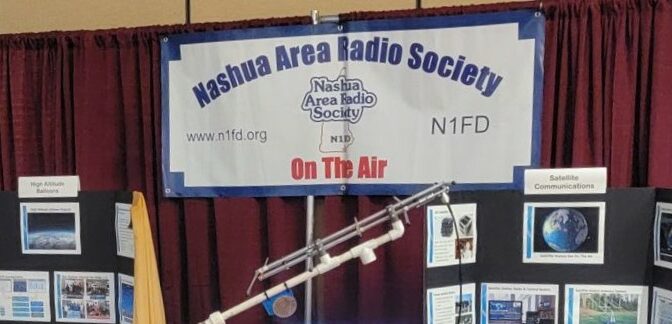
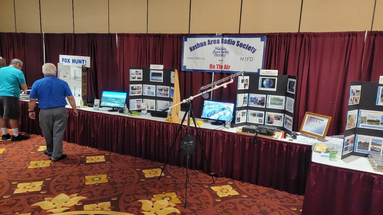
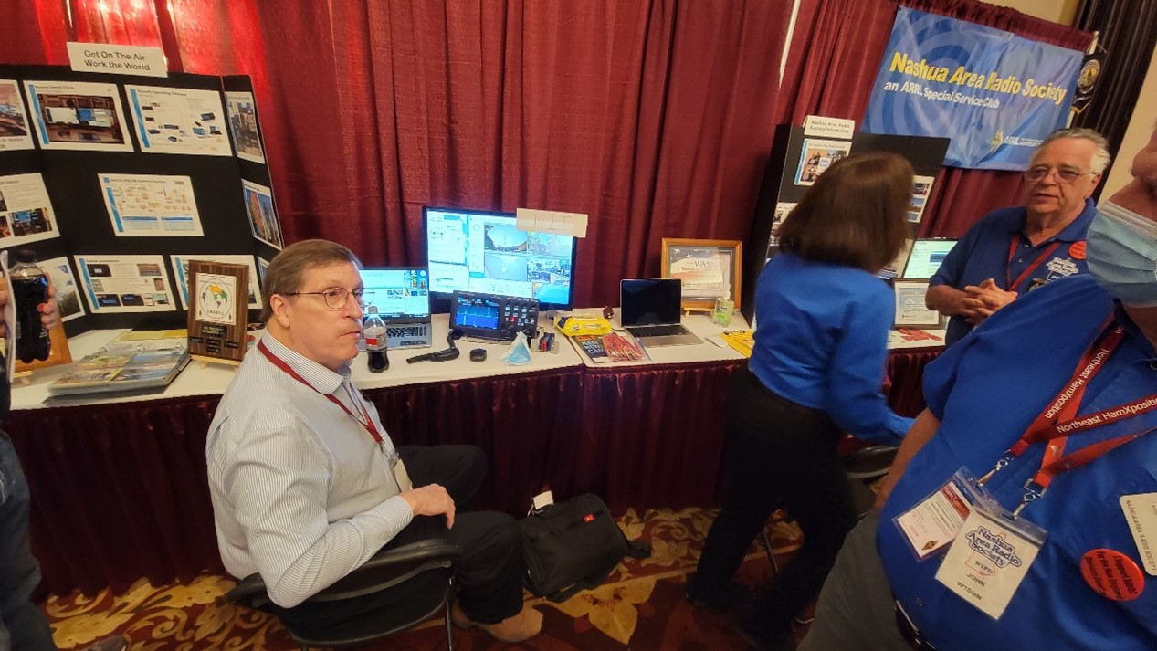
Stop by the Ham Radio Booth #103, inside Door 6 of the Better Living Center—then be part of and witness the exciting, live ARISS space station contact and astronaut Q&A in The BIG E Arena via Amateur Radio.
Visit this ARRL webpage for instructions on downloading a copy of your FCC license.
Download and print at home the 2022 Big E Brochure or 2022 Fairgrounds Map. Both are sized to fit letter-sized paper.