Given that Summer is in full swing and SOTA/POTA activating or hunting seems to be on everyone’s mind, I figured that an article on QRP portable operation was in order. One disclaimer, however… I am not a vastly experienced QRP portable op… I’ve dabbled in it and seen lots of YouTube vids (I guess that does make me kind of an expert)… and I do operate QRP from time to time. And, like a good pack rat… I have collected a few QRP rigs and their associated bling that I like to use.
A Little Background
SOTA/POTA
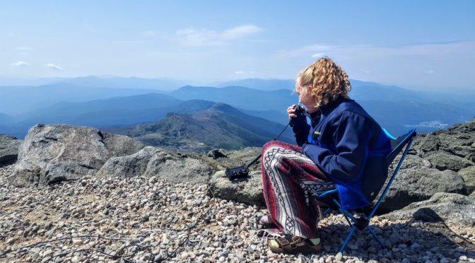
If you’re not familiar with SOTA, it stands for Summits On The Air, a “program” in which Hams go to summits and operate (It is kind of like the stricter, more formal cousin to the seemingly better known POTA or Parks On The Air). The SOTA web site at SOTA.org.uk describes SOTA as “an award scheme for radio amateurs that encourages portable operation in mountainous areas”. Both POTA and SOTA are typically done QRP, as QRP gear lends itself nicely to these activities… it’s lighter and more portable than an Icom 7300 or Yaesu FTdx10.
Although many SOTA operators spend all kinds of time trying to lighten their packs with the smallest setups possible… I am not one of them. I always overpack for any hiking trip (or at least my traveling companions complain that I do). As far as radio is concerned, when I am out “portable”, I typically operate out of my truck so weight is not an issue, so all my stuff is gonna be heavier. Also, I like my summits to be accessible via car… not that I am lazy (although my wife may disagree with that statement), it just happens that a nice hike generally takes me a while and seriously cuts into my operating time. That being said, I do have a few fairly light rigs if I really want to slim things down.
QRP
I think everyone is familiar with QRP operating, but if not… QRP refers to the use of low power when transmitting, typically five watts or less. QRPp is used to describe sub 1 watt operation (I am not that hardcore, nor am I a masochist, so I generally stick with 5 watts). Despite the reduced power, QRP is actually a lot of fun and has many advantages over higher-powered setups (especially for operating in the field).
Why Go QRP?
One of the main benefits of QRP is its portability. Because the equipment required to transmit at low power is generally small and lightweight, it can easily be taken to the field (and a side benefit is it can easily be hidden from your spouse). With QRP gear, it’s possible to operate from remote or rugged locations that might not be accessible with larger, more complex setups.
Another advantage of QRP is its simplicity. QRP equipment is generally less complex than QRO setups, which means that it’s generally easier to set up and use (as well as easier to afford). This makes it a great choice for field operation too. The transceivers are smaller and generally less expensive, tuners (if you use them) are smaller, and there are a host of CW keys that cater to the lightweight QRP crowd. These little gems can be as light as a few ounces. Since I don’t have the greatest dexterity in the world, I use a fairly large and hefty key… it weighs almost as much as each of my QRP rigs! Despite its size and weight, it fits nicely in my truck.
Despite its lower power output, QRP can still provide excellent performance. I have noticed, in my completely non-scientific testing, that I have not yet failed to complete a single QRP QSO. Now mind you, it may, and generally does, take me longer to complete a QRP QSO than it does to complete one at 100, 500 or 1000 watts. Stands to reason. But, it has never failed me. However, I generally only operate either CW or FT8 when QRP, rarely SSB. So, keep that in mind.
You do have to be patient though, and be mindful of who you are trying to QSO with. If you’re just on the air for some casual contacts or are activating a park or summit, you will likely do well and have fun. If you are trying to work a DX’pedition to a top 10 most wanted country, you might have some trouble making the QSO and experience what I once heard a Ham say about QRP… “with reduced power comes great frustration”. But, with the right attitude, QRP can be a lot of fun! QRP can be especially satisfying for those of us who enjoy the challenge of making long-distance contacts with minimal power… and it’s also fun to explain to your spouse the concept of dollars/mile when you want to pick up that new, “inexpensive” QRP gear.
Gear and Such
Obviously, when operating QRP in the field, you’ll not be bringing along your tower and yagis, or likely even your full-size multiband wire antennas. QRP operation in the field is generally about simplicity, ease of setup, and ensuring a low frustration quotient. Often wire verticals with a few radials are used in conjunction with a lightweight fiberglass mast, or, what seems to be more popular, is the use of End Fed Half Wave antennas (commonly called EFHW antennas). This is what I use. It is typically a ½ wavelength radiator connected to the radio, usually with a 9:1 or 49:1 transformer. For the more popular QRP bands (20, 30, and 40 Meters), it is a very manageable antenna.
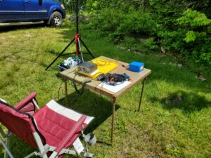
So this is a good time to talk about gear… that’s always fun, talking about gear (not as much fun as building or buying it and then using it though). Depending on what you want to do with QRP and where you want to operate, gear considerations can range from just a transceiver to an entire station.
For those that want to operate QRP from home, you likely have what you need already! Most HF radios can be dialed down to 5W or less. BINGO… you are running a QRP station. For those of us that want to bring our stations to the field, it is unlikely that we’ll drag our YaeComWoodCraftTec HF rigs (get it? Yaesu, Icom, Kenwood, Elecraft, and Ten Tec) to a campground, state park, or summit. So what’s a Ham to do? I am glad you asked…
Transceivers
Options
QRP transceivers can range in price from $14 (for a single frequency Pixie kit) to several grand for a new Elecraft rig. I advise staying away from the really cheap rigs though, as their performance is commensurate with their price (and they drive the frustration quotient wayyyy up). Many QRP rigs come in kit form, but if kit building is not your thing, there are many that you can buy pre-built. As well, most QRP rigs are either single band or limited to a subset of the HF range… typically 20-80M. Although, the more expensive rigs will cover the entire HF spectrum and even 6M in some cases. 20, 30, and 40 meters are the most popular QRP bands, and most QRP gear will operate there.
Manufacturers
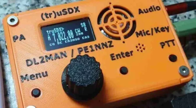
Elecraft has made and continues to make some very popular QRP rigs (such as the KX-1, KX-2, and KX-3), Yaesu has their FT-818 and 819 rigs, Icom has their IC-703 and current IC-705 rigs, LNR Precision makes the Mountain Topper line of QRP rigs, and MFJ made their Cub line of QRP rigs which you can sometimes find on Ebay, DL2MAN & PE1NNZ offer their (tr)uSDX line of SDR QRP rigs, and Xiegu makes some nice rigs including their G90 and X5105. There are literally hundreds of QRP rigs out there from dozens of manufacturers… Heathkit, Oak Hills Research, NorCal Radio, QRP Labs, Small Wonder Labs, Index Laboratories, etc. The list goes on and on.
Due Diligence
Unless you like being surprised though, do your research before buying a QRP rig. YouTube has lots of great vids on QRP transceivers. Google “YouTube Ham Radio Crash Course QRP”, “You Tube K4SWL QRP” “YouTube review <insert QRP rig here>”. eHam also has a product review forum that can be very helpful in making gear decisions, Check them out at Eham.net.
My Favorites
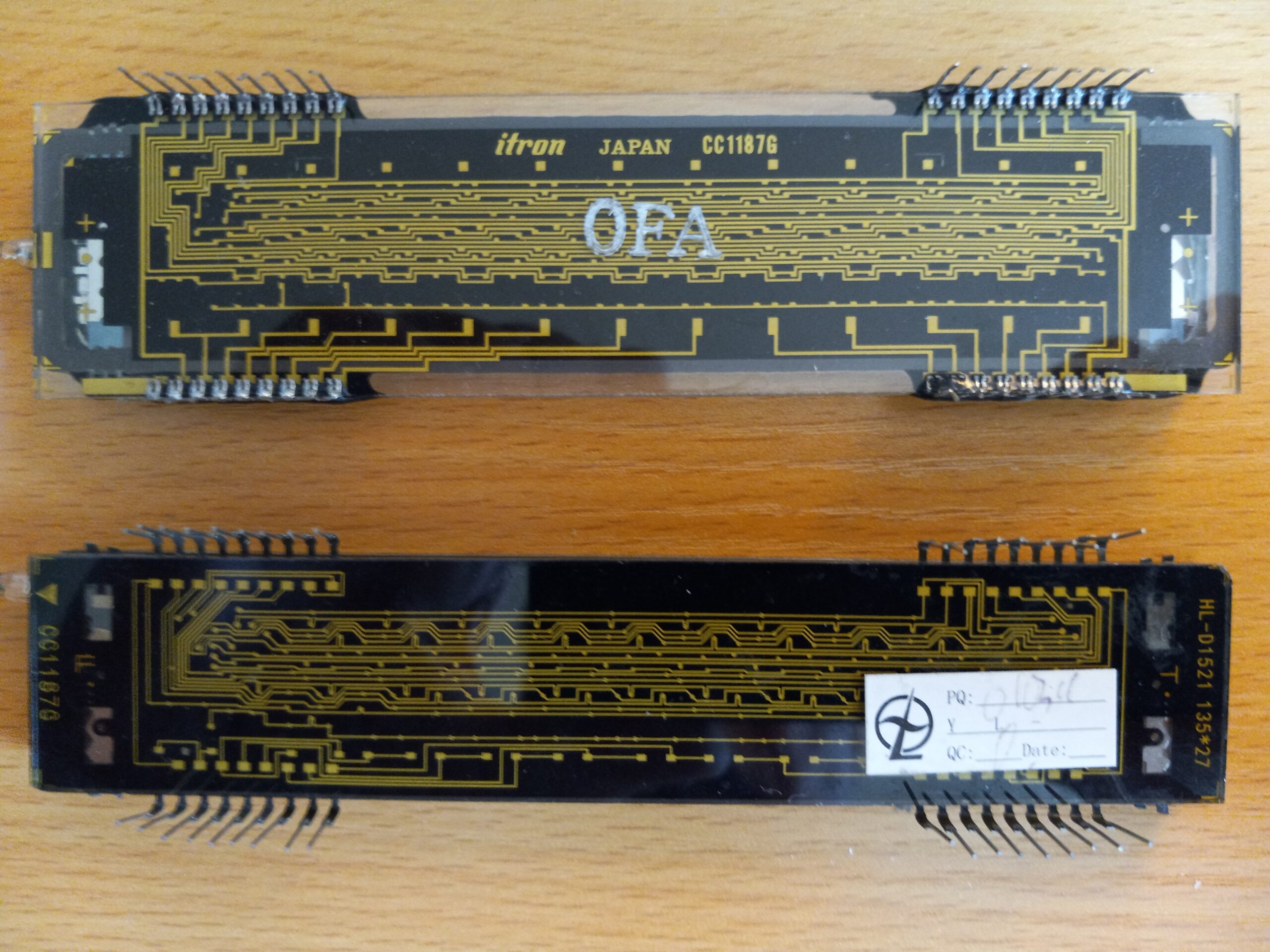
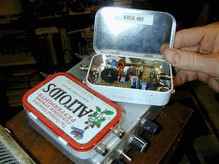
I have a number of QRP transceivers (none were particularly expensive) but my favorites are the (tr)uSDX, and the LNR Precision FX-2, as both are very portable and have features that I like. I also have an MFJ Cub for 30 meters, which I like but it takes ~30 minutes to warm up to become frequency stable… not a good field radio.
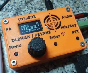
The (tr)uSDX is a multi-band, multi-mode rig covering 20-80 meters with a maximum of 5w out. It operates SSB, AM, CW, and digital (with the right interface). It has a lot of really slick features for a sub $200 HF rig.
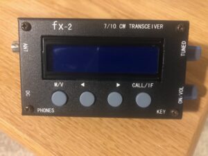
The FX-2 (which is no longer made) is a 30 and 40 meter CW only rig with up to 5w out. It is built like a tank with some cool features as well and cost me $70. I bet you already know a Ham who has their own favorite QRP rigs they’d love to tell you about!
Power Sources
Batteries are the most likely power source for QRP in the field. While many of the more expensive QRP rigs have internal batteries, most use an external power source. You can use literally any battery that provides the right voltage and current, and most QRP rigs operate anywhere from 8 to 12v, with reduced power below 12v, and draw less than 1 amp on TX. A very popular external battery type used by many QRP ops today are rechargable Lithium Iron Phosphate (aka LiFePO) batteries. They are extremely light, very portable, and perform exceptionally well. A nice accessory to your LiFePO battery is a solar charger. If you plan to spend lots of time in the field, that may be a worthwhile investment. I have found Amazon to be a great source for LiFePO batteries.
Keys
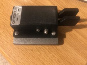
If you are a CW op, I am guessing you are very particular aboutyour keys (aren’t we all). I am a Bencher guy… since I got my ticket, I have used only Bencher Iambic paddles at my station… but they are really big, really heavy, and a pain in the neck to carry around for portable operation. Although I don’t own any, I know that Vibroplex bugs are the same, and many straight keys are a bit cumbersome too (although not as much as bugs or “traditional” paddles).
There are a number of places to get small, lightweight keys for field use. Google it, and you’ll get some options. But I’d like to save you some time (cuz I am a nice guy). Check out CW Morse and have a look at their line of keys. I have their double paddle with a base, and a Camel Back straight key. Both are made very well, and a joy to use… and they fit nicely in my truck. Are there smaller, lighter-weight options out there from them and others? Yep. But I really like and recommend these.
Antennas
Here’s where the sky is the limit (pardon the pun… I couldn’t help it). QRP antennas run the gamut from loops, to horizontal wires, to verticals, to portable beams. In general however, portability and ease of deployment are key to success in the field. That is what makes the EFHW such a popular QRP field antenna.
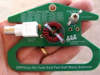
EFHW’s are very easy to build and if done right, don’t require a tuner (and to make it even easier, you can buy the transformer in a nice kit). QRPGuys.com sells a bunch of QRP EFHW transformer kits. I have the 10-80m no tune kit. You should check them out . If you are only interested in operating on one or two bands, cutting elements for each band makes sense. But what if you want to operate anywhere from 10-80 meters? Cutting and carrying elements for all of those bands is tiresome, cumbersome, and unnecessary. Enter the “linked dipole” concept for an EFHW antenna.
Linked EFHW
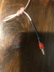
What is a linked dipole? I am glad you asked… according to VK7BEN, a linked dipole “provide[s] the benefit of creating a single-wire antenna that is resonant on multiple bands without a tuner by “linking” together lengths of wire with clips.”. However, I use banana connectors and small carabiners on my linked EFHW. I also found that 18-22 gauge speaker wire works really well for portable EFHW elements.
Building a Linked EFHW
Here’s how to build my version of the linked EFHW.
- Determine the full element length for each band you want to work.
- Cut the element for the highest band you want to operate (i.e. 20M) at it’s full length.
- Next determine the difference between the full length for the next highest band and the previous band (i.e. 30M – 20M).
- Then cut an element for that length.
Do this for each band you want to work.
For example, if you want an antenna for 20-40M, here’s what you would do:
- 20M full length: 28’ 8”
- 30M full length: 42’ 6”
- 40M full length: 61’ 6”
- Cut an element to 28’ 8” (this is your 20M or “base” element)
- Cut an element for the difference between 20 and 30M (13’ 10”), this will be your 30M “linked” element
- Cut an element for the difference between 30 and 40M (19’), this will be your 40M “linked” element
I soldered a small ring connector to one end of the 20M element to attach to the QRP Guys transformer kit at the post and wing nut.
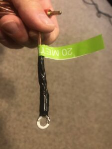
On the other end, I made a small loop by tying the antenna back on itself, and then attached a male banana connector to the very end.
I did the same to each end of the 30M element and to one end of the 40M element too. To the other end of the 40M element I simply made the loop, but did not add the banana connector. This is where I attach the “hoist rope” for getting the antenna into the trees.
I have 150 feet of 1/4” line that I use to hoist the antenna into the trees. To one end, I attached a light carabiner.
Using the Linked EFHW
To operate 20M, I simply attach the 20M element to the transformer using the ring connector. Then I attach the carabiner at the end of the hoist rope to the looped end of the 20M element, and pull it up. If I want to operate 30M, I use a female / female barrel connector to electrically attach the 30M linked element to the 20M element. A light carabiner physically connects the two elements at the loops. This provides strain relief for the banana connectors..
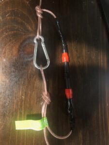
For 40M, I attach the 40M linked element to the end of the 30M element (which is attached to the 20M element) in the same way and connect the hoist rope to the antenna with a carabiner.
There are many ways to construct a linked antenna. I like this design because, unlike traditional linked dipole designs, which use a “trail line” to deploy all of the elements at once having a length equal to the longest band element, this allows me to only deploy the elements that I need, making antenna deployment overall simpler IMO. I happen to like simple, it is less taxing on my brain.
As with any antenna, resonance can be affected by many factors, but I did not find any impact to the resonance of the elements by tying them back on themselves for the end loops.
Antenna Tuner
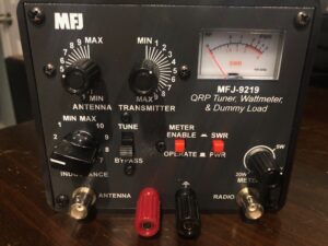
While it is best to not need or use an antenna tuner, especially when running QRP power levels, sometimes it cannot be helped. Unless your rig has an internal antenna tuner, there are really two options for tuners… automatic or manual. LDG makes some nice auto tuners and one specifically for QRP, the Z-817. Personally, I find external auto-tuners kind of pricey for dragging them out to the field, plus it is one more thing requiring a battery. Although I never want to have to use it, in case I do need one, I keep an MFJ-9201 manual tuner in my kit. The key for tuners is get a small, light-weight one. Make sure, if it is an auto tuner, that your radio can provide the needed power to activate it. Some auto-tuners will not activate below 5W.
Computer
Who needs a computer in the field! Well, if you want to work FT8 from that shiny new QRP rig, you do. Also, I find logging on a computer to be much easier than doing so on paper. No need to re-enter it all into my log at home when I get back. Plus, my handwriting is atrocious, and often, even I can’t decipher what it says, so I save myself the trouble.
Really, any portable computer will work for logging. From Apple and Android phones, to tablets, to Windows laptops, to Linux devices. As long as they have decent battery life, and some logging software available for them, they should work. I use an older Lenovo Chromebook that I converted to Linux, and log with CQR log. When I get home, I export to an ADI file and import the QSO’s into my home logging software. Because it is a tablet with an O/S that supports WSJT-X, the Lenovo also has the benefit of allowing me to work digital modes such as FT8 as well.
One thing to keep in mind though, paper logs are easy to read in direct sunlight; not so much for many device screens (ask me how I know).
Packs
Now that you have that sweet QRP field kit, how do you get it where you’re going? Well, this is the topic of hours and hours of YouTube videos. Backpacks are the most reasonable answer if you’re going into the bush, but, if you are like me and going into the bush means driving to a place with trees, you might want to consider something else.
I’ve seen many cool QRP field setups carried in Pelican cases, or the less expensive Apache cases from Harbor Freight. One benefit to them is that your stuff is well protected if you tend to drop things (again… ask me how I know). In addition to Apache cases, I also use a small “range” bag that can be found at most sporting goods stores or online. It has lots of pockets and is easily carried. It also fits nicely in my truck when I am going into the bush.
If you are a backpack person, there are literally dozens of options. If you need to kill a week or so of time, Google “Best backpack for QRP” or “Best backpack for SOTA/POTA”.
There You Have It
That’s the 411 of QRP and building out a basic QRP field kit. Of course, your kit can be anything from minimalist to extravagant, but, you don’t need a lot of gear or money to have some QRP fun. The key, especially if you are interested in going outdoors with your gear, is simply to do it. QRP gear is the perfect companion to a day at the park (or even a few hours grabbed at the end of the work-day).
Operating QRP can be a lot of fun simply because it’s a challenge. In my opinion, operating QRP successfully, builds out a set of skills and techniques that will also make you a better QRO operator. And, there is certainly a sense of accomplishment that comes from successfully communicating with others using minimal power.
Whether you plan to operate, watch and learn, or just hang out and socialize; I certainly hope to see you at the upcoming NARS SOTA activations. Unless I have to travel, I plan to be there and exercise my field kit. Of course, I’ll be driving up.