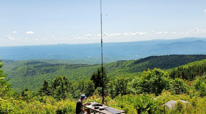
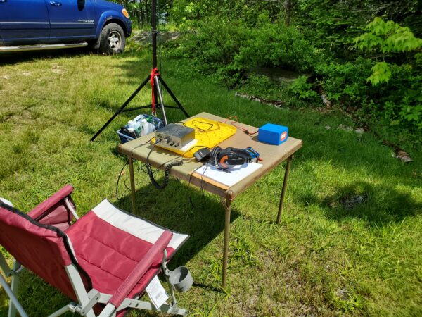
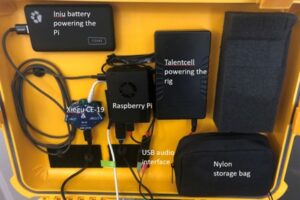
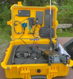
One of the problems I face when I think of doing a POTA activation is what to bring and how best to organize my gear so I have what I need. The easiest thing to do is consider what you MUST have in your POTA equipment cache. Secondly, list the necessities to get your station on the air in the field. If you forget to bring the manual for your transceiver, some coax adapters, or various lengths of complete jumper coaxial cables, it might make the difference in whether or not you get on the air. I have two ‘bags’ plus my accessory bag containing everything I need to get up and running.
The first ‘bag’ is a hard case for my HF rig, VHF/UHF HT, power source, microphone, keyer, and antenna analyzer. Also included in this case are the operating manuals for the HF rig, the VHF/UHF HT, the power source, and the antenna analyzer.
The second ‘bag’ contains my antenna and coax. Within the confines of this small bag is my “Super Antenna” vertical, the precut-tuned radials from 80m through 10m. A mounting tripod, a ground spike antenna mount, a locking plier with a 3/8” to SO-239 connector welded to it, an HF frequency chart, and a 25’ length of RG-8X coaxial cable with PL-259 for the connection to the antenna end and a BNC connector on the other end for the input to my KX2 Rig. Plus, the tools to set the antenna up and set adjustments.
My accessory bag has various items I have sometimes seen needed on a portable radio setup. Although I am new to the POTA activations and hunting them, I have operated from many field locations in my 66 years as a ham radio operator.
MY GO-BOX CHECKLIST:
-
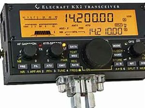
Elecraft KX2 Elecraft KX2 w/KXPD2 keyer paddle & MH-3 Mic
- Wouxon UV3D 2m/70cm HT & Whip Antennas
- FlashFish 200W Solar Generator
- Heil BM-17 earphones
- Vibroflex Vibrokeyer CW paddle
- AA-30 Antenna Analyzer
- Solar-powered clock/thermometer
- LED Light powered by Solar Generator
- Frequency Reference Guide
- Mini Log Book
- FCC License
- Elecraft KX2 Manual
- FlashFish Solar Generator Manual
- AA-30 Antenna Analyzer Manual
MY ANTENNA GO-BAG LIST:
MP1C Super Antenna includes:
- TM1 Low-Profile Tripod
- UM2 Universal NVIS Super tilt Clamp Mount
- SW1 Titanium Super whip
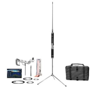
MP1TRDX80 Superantenna - SP3 Super Spike Ground Mount
- MC80 80-Meter Coil
- MR Super Radial Sets = (40m-10m); (30m-17m); (80m-75m); (6m-4m-2m)
- FG1 SWR Ruler
- GB2 Super Go Bag
- ER1 Extension rods
- TW1 Telescopic Whip
- PC1 HF Propagation Chart
- Clamp and U-Bolt
Tools:
- Hammer
- Allen wrenches
- Long-nose pliers/wire cutters
- Adjustable crescent wrench
Extra Antenna items:
- Locking pliers with 3/8”- SO-239 fitting
- ~ 90’ of Extra flexible antenna wire
- SIZE: The antenna extends to about 8ft tall. Collapsed Size: 12 inches. Go Bag Size: 13″x9″x3.5″ WEIGHT: The antenna weighs 1 pound. The antenna with accessories in the Go Bag is about 5 pounds. Maximum Power Rating: 500W SSB, 300W CW/DATA.
- FREQUENCIES: ALL BANDS 80m, 75m, 40m, 30m, 20m, 17m, 15m, 12m, 11m, 10m meters (3.5MHz to 4.8MHz and 7MHz-30MHz) HF, plus VHF 6m (30MHz-54MHz) with a good SWR. Continuously tunes all frequencies: Marine, Government, NGO, CAP, MARS, EmComm, Shortwave, CB, etc. Direct Manual Tuning SuperSlider Coil, with Good SWR.
- ANTENNA: The MP1C Antenna is at the heart of this high-performance system, with its high Q coil made of military-grade nickel beryllium resulting in repeatable precision.
- TUNING: The FG1 Frequency Guide SWR Ruler calibrates a rigid polymer card in MHz and meter bands. With it, a good SWR is dialed in on all HF and VHF bands and then fine-tuned with my AA-30 Antenna Analyzer. There’s no need for an autotuner, but it can help extend the frequency range.
- SUPERWHIP: The included SW1 ruggedized Titanium SuperWhip puts the Super Antenna in a ruggedized durability class beyond most regular ham antennas.
- TRIPOD: The collapsible TM1 Low-Profile Tripod enables the antenna to be set up on any convenient flat surface, outdoors or indoors.
ACCESSORY BAG CONTAINS:
- 30-watt soldering iron w/solder
- 3M waterproof Super 88 electrical tape
- 3’ 50-Ohm BNC/BNC Coax Jumper Cable
- 2’ 50-Ohm PL-259/PL-259 Coax Jumper Cable
- AA Battery Pack for Wouxon UV3D HT
- Assorted VHF/UHF, BNC, and SMA adaptors
- AC/DC Power supply for KX2 and External Lithium-Ion
Fast Charger for the KX2’s KXBT2 battery
- Wouxon UV3D battery charger
- Bongo ties
- LED flexible lamp
- Multimeter
- RCA to twin RCA splitter cable
- USB to Micro cable
- 5mm to 2.5mm 6’ audio cable
- Programming cable for Wouxon UV3D
- USB cable with AC to 5 VDC adapter
- 2-Meter flexible J-Pole antenna w/BNC/PL-259/SMA adapters
- Mini-bud earphones
- External battery for cellphone – 9.6-watt hours – 5VDC in/5VDC out
- Wall-wart power supply charger for Solar Generator 110/240 VAC in/15.0 VDC out
- Transient voltage surge suppressor
- MFJ Model 281 ClearTone external 8-ohm 4” speaker
- 25-watt dummy load
- Extra 2m/440 whip antennas
When building the case for the KX2 and the other items, I chose a hard-sided, oversized briefcase instead of a Pelican Box. I reasoned that I didn’t see the need for that order of protection with the way I operate on POTA activations. History may change my mind, but it has been more than adequate to serve my needs so far. I bought the case at Harbor Freight for $40.00. It came with pre-sliced foam for the bottom and an acoustic-like foam rubber top panel. The precut foam made it easy to make exact-size cuts to insert my Solar Generator and the KX2. The divider strips came with breakable stops to make it easy to make custom-divided sections in the case. I made a door-like cut in the top panel, and with Velcro, it now serves as a storage area for my manuals and paperwork. The total weight is around 15 pounds when loaded. Most of that weight is attributed to the 200W Solar Generator, about 4 pounds alone.
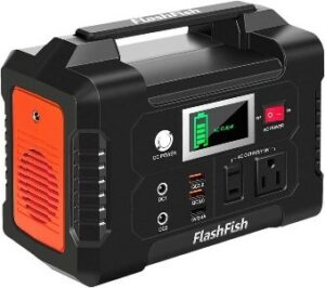 The internal KXBT2 Lithium-Ion battery pack In the KX2 provides 11 VDC @ 2.6 Ah, giving you about 8 hours of operation. It slowly recedes in power as the voltage decreases. The Solar generator plugs into the DC input of the KX2. When the power is less from the Lithium-Ion battery than the Solar Generator output, the KX2 automatically switches to the more prominent voltage source. I have a 100-watt foldable solar panel that inputs to the Solar Generator. However, you can’t charge its battery while it is running. Multiple Charging Outputs on the Generator Provide More Options: Features with AC/ DC/ USB OUTPUTS: 110 VAC output (200W), 2 DC outputs, 2 QC 3.0 quick charge USB ports, and 1 USB port (2.4A auto). It provides 151Wh (40800mAh) to power your transceiver, smartphone, tablet, laptop, camera, light, drones, fans, in-car appliances, CPAP machine, and more anytime. Triple Rechargeable Modes = Efficient Solar Generator: FlashFish power station’s Lithium-Ion battery pack can be charged by a 15-24-volt solar panel (not included), AC wall adapter, and car charger efficiently. There is no memory effect and no worry about battery capacity reduction.
Other ite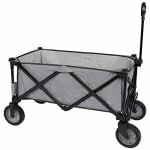 ms worth bringing along for your activation should include a lightweight, foldable table and a comfortable folding chair. A pop-up canopy is also a good idea if the weather is too sunny or the weather turns to rain. With all this gear, you might want to invest in a foldable wagon to haul it to your chosen spot after leaving your car. They typically cost about $70, but you will also find many uses around your home for them caring for household chores and at hamfests carrying about your newfound ‘treasures.’
A solar-powered 24-hour clock set to UTC gives me the exact time and the corresponding UTC date whenever I log my QSOs in a paper log book.
I now bring a wireless ‘Hot Spot’ from my cellphone carrier on these POTA activations. I can run my logging program on my tablet and use the wireless keyboard. I can still be online because I’ll have an Internet source at a reasonably remote location in the ‘Great North Woods’ of New Hampshire, Vermont, or Maine.
Although not required, legally, having a photocopy of your FCC license handy or mounted somewhere on your Go-Box is a good idea. If law enforcement, park rangers, etc., question what you are doing, it usually alleviates their concern about your presence and actions once a Federally-issued license is recognized. If you are entering a State or Federally-owned National Park, it is always a good idea to ask the person at the entrance about your antenna and whether they have any rules about using the trees as a support source.
Always try your gear at home or a nearby field location before heading out on your outdoor radio adventure. Set it up approximately the same as you will at the POTA event. You will be better prepared after doing so and could benefit from any faux pas you encounter during this practice session.
73 es GL de Jack WMØG