Category Archives: Station Equipment

Articles about Radios, Amplifiers, Tuners and related Ham Station Equipment. Fixed, Portable and Mobile Station Equipment Articles are included.

Satellite Station Antenna Upgrades

We’ve been making good use of our Satellite Ground Station. Our existing 2MCP14 and 436CP30 antennas have enabled us to make over 2,000 satellite contacts; working 49 of the 50 U.S. States, 290+ Grid Squares, and 31 DXCCs. Our station is also an ARISS Ground Station which enables us to help Schools around the world talk to astronauts on the ISS.

As you can tell, we are pretty active on Satellites so we decided to take our station up a level by upgrading our antennas. We choose larger yagis with booms over 18+ ft in length. The upgrade required us to improve the mechanical aspects of our Satellite Antenna System as well…

Source: Satellite Station 4.0 Part 12 – Antenna Upgrades

We’ve been pretty busy with antenna projects at AB1OC-AB1QB this fall. In addition to building a new EME Antenna System and Station, we’ve also been working on upgrading our Satellite Antennas.

Satellite Antenna Upgrade

The Satellite Antenna project was a pretty challenging one. We opted for the largest available circularly satellite antennas available from M2 Antenna Systems.

Satellite Antennas On the Tower - Parked
Satellite Antennas On the Tower – Parked

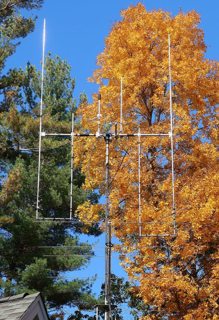
Getting these antennas to be mechanically reliable, properly aligned, and operating smoothly required us to make some custom modifications to the hardware associated with our Satellite Ground Station.

Cross Boom Counterweight and Trusses

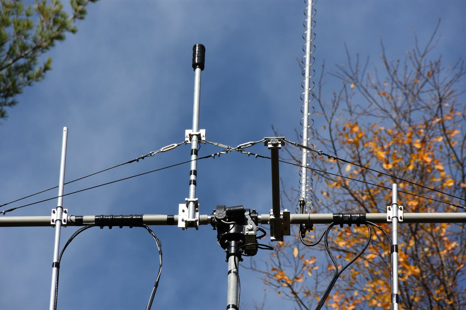
The article above covers the construction and adjustment of the new antennas. It also covers several custom enhancements that we made to our satellite antenna support system.

Aircraft Tracking Antenna System Addition

Satellite Tower Infrastructure including ADS-B Antenna

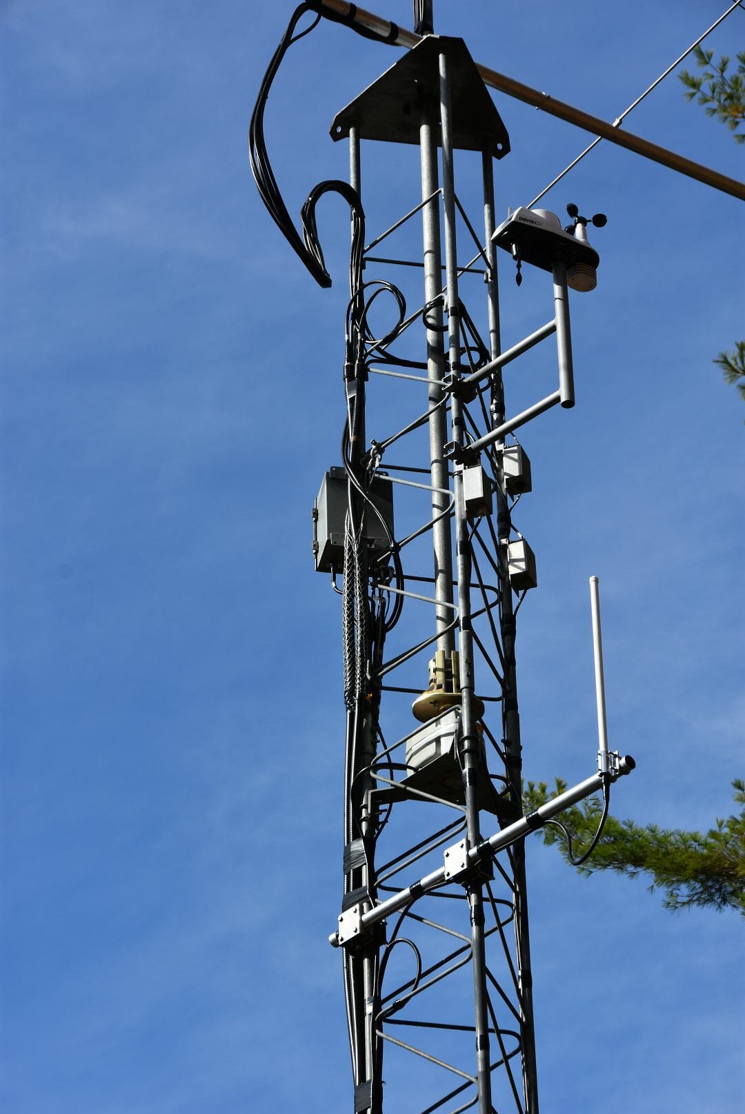
We also added an outdoor antenna for our FlightAware ADS-B Tracker as part of the project. ADS-B is a relatively recent aircraft tracking system. Our new ADS-B antenna has increased our Tracker’s contribution to the ADS-B network considerably.

If you’ve ever wondered what goes into building and putting up a high-performance satellite ground station, take a look at the article. The ideas shared there are applicable to the construction of any VHF and above antenna system – especially those that utilize elevation rotators and thus require balancing.

Fred, AB1OC

EME Station 2.0 Part 12 – Station Software

Software is a big part of most current EME stations. The JT65 Protocol, which was created by Joe Taylor, K1JT, has revolutionized EME operations. It has made it possible for modest single and two yagi stations to have fun with EME…

Source: EME Station 2.0 Part 12 – Station Software

Operations using EME or Moonbounce communications is all about software. Every station’s software architecture and configuration is a little different.

2m EME Software Block Diagram - Phase 1
Station Software Block Diagram – Phase 1

We recently put together our software suite for our new 2m EME station. Our setup features multiple JT65b digital decoders, automatic tracking of the Moon, computer logging, and some useful web-based tools that make finding QSOs easier.

EME Software Operating Environment
EME Station Software Operating Environment

Our Phase 1 station configuration is mostly about integrating all of the components in our setup, sorting out operational issues, and learning to use all of the new software and hardware in our new Station.

MAP65 Software
MAP65 Software

Our primary software application is MAP65. This program can decode all of the signals on a given band at the same time. This is very useful during an EME Contest and for finding contacts during day-to-day operations.

You can read all about our software setup for our station via the link above.

Fred, AB1OC

The Sound Card

The Sound Card and How it Works

For a ham radio operator trying to work the digital modes for the first time, half the battle is installing the software and learning how to make it work. The other half of the battle is installing the Sound Card,  making all the right adjustments, and trying to make that work successfully. However, if you have one of the newer ICOM, Yaesu, or Kenwood radios, that struggle is almost eliminated as they have their sound cards built-in.

But, if your transceiver doesn’t have one, you’ll need to come up with something that takes the audio from the computer and run it into the radio; and then from the radio and back into the computer.

Basic Sound Card with Dongle

As shown above, the cheapest way to deal with this is to buy a USB audio dongle from eBay for about $ 3 and then a sound card kit for about 10 bucks. And finally, you’ll need to purchase a few 3.5 mm cables to connect from the dongle to the sound card. Then the fun begins, trying to figure what cable goes to where.

Inside the Sound Card

Essentially, a sound card is a device that takes the audio produced from the computer, matching the impedance between the computer and the radio and attenuating the signal considerably. Otherwise, the audio signal would be too strong for the radio to work properly, overloading the distorting it. Likewise, when sending a signal back from the radio to the computer, the audio has to be controlled and the impedance matched between the two pieces of hardware.

Typical Sound Card Schematic

The schematic above shows the audio coming from the USB dongle into a resistor divider network, at R3 and R4, which steps down the signal by 100 to 1. Then the audio goes through T2 for impedance matching. At the input and output to T2, there are capacitors used for shaping the signal going from the computer to the radio.

Going from the radio back to the computer, the schematic is similar; it uses a transformer, T1, used for impedance matching.

On better sound cards, potentiometers are used for further adjustment for the inputs and outputs.

Some sound cards provide for the capability of operating the PTT circuit by taking the control signal off the DB 9 connector on the computer and sending it to an optocoupler on the sound card. This is used to separate any difference of potential which might exist between the two pieces of hardware.

A Better Solution

Signalink USB

Of course, the easiest way to deal with this is to purchase something like the Signalink USB card from a supplier such as Ham Radio Outlet for about $ 125. The advantage to this card is that it plugs directly into the USB connector on your computer – eliminating the USB dongle –  and then connects to the radio with a special DIN connector at the other end. Also, this card has individual controls for TX, RX, and Delay.

Final Adjustments

Enough can’t be said about the need to make sure the right audio levels are set for the inputs and outputs at the computer and the radio. If the audio is too strong going into the radio, your transmission will distort, making QSOs harder to get. And at the other end, if the input signal is not at the proper level to the computer, the software will not be able to pick up the incoming sound.

My hope here is that with a little understanding of the sound card and what it does, this will make your next QSO on one of the digital modes as smooth as possible.  With some trial and error worked out, your next contact will be a lot easier. 73

Randall N1KRB


Radio Amateurs Developing Skills Worldwide