Last week I gladly accepted a free Azden 2m FM transceiver model number PCS-4000 that was offered to me. You have to love the old free stuff! The only capability this 25W rig was missing is the ability to transmit CTCSS PL tones or sub audible tones to activate a repeater.
I found the manual and schematics online and found that this rig was built to accept a tone generator as an add-on. See below.
Below is a photo showing the jumper locations for the tone input. I soldered some leads with a home brew disconnect to easily remove the cover in the future.
Below is a photo showing an added 1/8″ mono jack for the input tone.
For an input tone, I used an Android cell phone with a frequency generator App to generate the PL tone.
I can experiment with other ways to generate the tone such as an Arduino with RC filters etc. I can also try to insert a 700 Hz tone with my Arduino keyer for MCW.
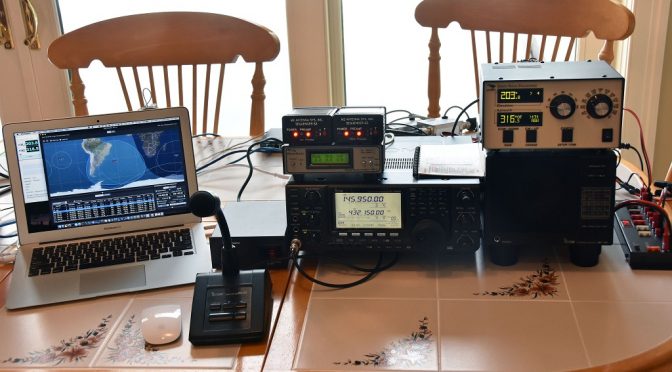
Below is a photo of the rig set up for a local repeater.
So now to quote Pete Juliano “Bob’s your uncle”!!!
The Icom IC-9100 provides 100W on 2M and 75W on 70 cm which is more than enough power for our application. It also has some nice satellite features such as support for synchronized VFO tracking between the 2M and 70 cm VFOs on the radio. This radio also uses a single USB connection to allow computer control of the radio and creation of a sound card interface on the host computer. A Heil Proset 7 will be used for operator audio to avoid feedback due to our audio coming back from the satellite. The Icom SP-23 speaker is included to allow observers to hear satellite contacts while they are in progress.
Radio Management via MacDoppler
The MacDoppler software provides automated control of the IC-9100 including mode selection and automatic correction of both VFOs for Doppler shift. These features greatly simplify the operation of the radio, especially when satellites with SSB/CW transponders are used.
The video above shows MacDoppler’s management of the IC-9100 Transceiver during a pass of AO-73. The constant adjustments of the VFOs take care of Doppler shift correction and ensure that our signal stays at a fixed position in the transponder passband of linear transponder satellites.
Preamp Sequencers and Output Monitoring
M2 Antenna Systems S3 Sequencers are used to provide control of the Advanced Receiver Research low-noise preamps on our portable tower. One of the nice features of the Icom IC-9100 is that it can be configured to provide separate keying lines for the 2M and 70cm VFOs. This allows a preamp to remain enabled on the receive VFO while the other VFO is in transmit mode with its preamp shut down by the sequencer. This arrangement is very useful during tuning when one needs to hear your own signal coming back from a satellite. A custom-made cable assembly was made to interconnect the S3 Sequencers with the ACC socket on the IC-9100, the Weatherpack connector on the tower preamp control cable, and DC power.
We used the excellent WaveNode WN-2 Wattmeter again in our portable satellite setup. This is a modular output monitoring system which has a sensor for VHF/UHF use as well as voltage, signal quality, and other monitoring functions.
DC power for the setup is provided via a Powerwerx SS-30DV Power Supply and a RigRunner 4007U distribution unit. We use this power supply in all of our portable setups. It is light weight, provides plenty of power for a 100W station and accessories, and is quiet from an RF perspective.
Equipment Packing and Protection
With the transceiver test of the station complete, we turned our attention to transporting the setup. Proper protection of the equipment during transport was provided via a large case from Pelican. We combined this with a roller bag and an inexpensive storage bin for documentation and accessories which are not very fragile. We also included our RigExpert antenna analyzer in the setup to make testing of the station during setup in a portable environment easier.
Station Packed and Ready for Transport
With all of the assembly and testing of the components of our 2.0 Portable Satellite Station complete, we packed up all the components. We used an inexpensive furniture dolly to allow us to roll the tower around to load and unload it.
We are ready to test our new station in a portable application. More on that in the final article in this series. Other articles in the series include:
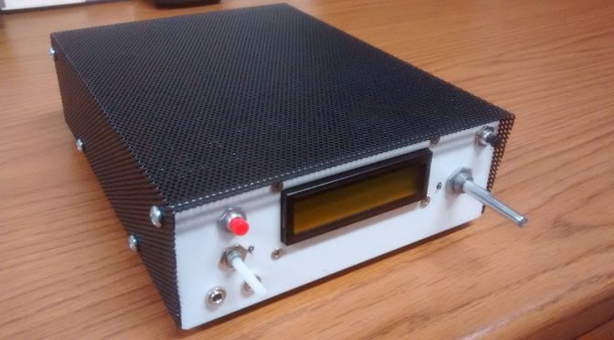
Below is a photo of my BitX-40 kit from Ashhar Farhan VU2ESE in India with my very own custom designed case. The kits are available from http://www.hfsigs.com/
The top cover shown is powder coated steel mesh.
The sheet metal housing was designed in a solid modeling software package called Onshape. This web based software is free to use if your designs are to be available to anyone who signs into an account. This design is “in the cloud” and considered “open hardware”, available to anyone who would like to use it. Below is a screen capture of my Linux desktop running Onshape within a web browser.
With access to a CNC punch press and a 90-ton brake press, a coworker of mine helped out with a bit of “government work”!
I left out some of the detail in the housing to let others enjoy the use of a drill and allow for some creativity with a customized placement of components.
Some of the wires are not needed but may be useful in future “hacks”. The image below shows some of the wires removed from the “Molex” connector. A small sharp object can be used to push in on the barb to remove the contact for a future project.
I used my sketch to drive the LCD screen and the SI5351 chip using the Adafruit library. The checkered block moves left and right between the arrows to indicate when I am at or near the end of travel with the tuning potentiometer.
Stationary
When I move the block all the way to the right with the potentiometer it turns into an arrow and automatically increases the frequency. To make it stop just turn the potentiometer to the left.
Frequency rising
I like the ability to scan the band without having to turn a knob!
Below is an image showing 12v and 24v voltage regulators and electrical tape on the housing tabs. 12v is for the majority of the wiring and I used 24v for the IRF510 PA. The black tape looks nice behind the black mesh cover. while testing I measured about 4W RF output with 12v feeding the PA and 16W RF at 24v.
The bottom has extruded “feet” along with stick on feet to keep the rig from sliding.
I used an SO-239 connector for the antenna. I saved the BNC connector from the kit for test gear. The red terminal post is connected to 32v from a repurposed HP printer power supply. The barrel jack is connected to 16v from the same supply.
For more information on the case, you may contact me through my QRZ page.
We use cookies to ensure that we give you the best experience on our website. If you continue to use this site we will assume that you are happy with it.