Category Archives: Station Equipment

Articles about Radios, Amplifiers, Tuners and related Ham Station Equipment. Fixed, Portable and Mobile Station Equipment Articles are included.

Bigshot Slingshot Throwline Launcher for Raising Wire Antennas

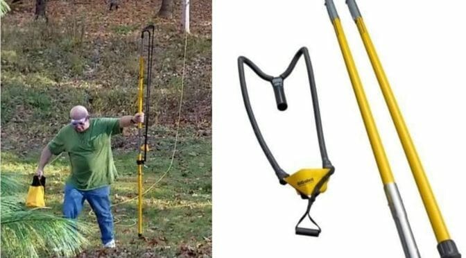
Bigshot Slingshot to launch a line for an antenna

There are several tall trees at my NH QTH and I decided to put an antenna up as high as possible in one of them. I needed a way to accurately put a wire high up into the tree. I read about spud cannons used to launch a line up for an antenna and considered buying or borrowing one for the project. Around this time, I saw a device called a Bigshot Slingshot Throwline Launcher on a TV show about building treehouses and it intrigued me. It is heavy duty and can throw a 10 oz. or 12 oz. weight with a 3/8 inch line attached up 100 feet or more.

Bigshot Slingshot
Bigshot Line Launcher

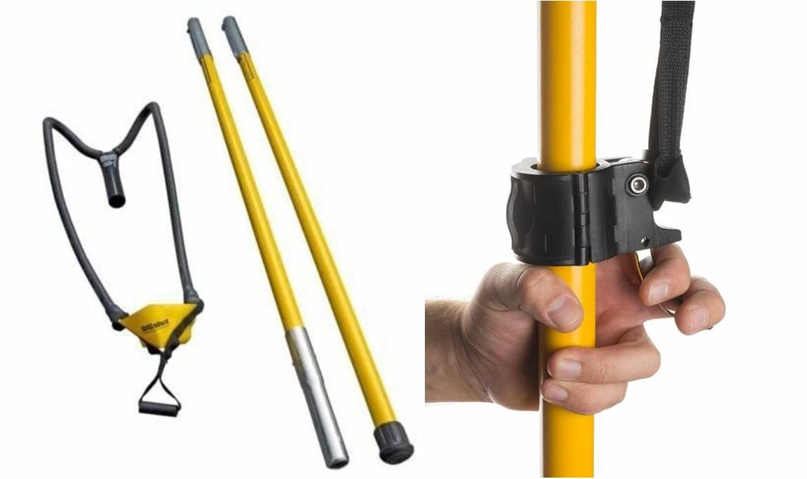
I found a deluxe kit on Amazon which contained the slingshot and trigger assembly along with spare elastic bands, throw weights, line, line bag, and carrying case. It is built robustly, to commercial standards and I was eager to try it out. I did a few dry runs and learned that it could easily launch the weight 75 feet up. For more height, set the trigger assembly lower on the pole to stretch the elastics more and launch even higher.

Caution!

An Important Word of Caution Here!! This device is powerful and can cause injury if not used carefully. Read all the instructions, wear eye protection, and like a gun, point it away from anything you do not want to break. I am 6’2” and 275 lbs. when cocking the elastics and straining against their pull this device lifted me from the ground and pulled me off balance with ease. I have a lot of respect for the power it has and you should too.

End Fed Half Wave Antenna at 50 Feet

I previously used this line launcher to install a MyAntennas.com 8010 EFHW antenna in my NH QTH backyard with the endpoint up in a tree 50 feet high. I was happy with the performance there for 6 months until I tried working in the CQ SSB DX WW contest. Before the contest, I logged QSOs on 20 and 40 meters all over the US, South America, Africa, and Europe, along with some 80 meter QSOs out to around 1500 miles. However, during the contest, I had difficulty breaking pileups, so I decided to try and raise the tree end of the antenna.

Preparing to launch the line

Bigshot Slingshot
Old rope in the tree

The line hanging from the tree is what held the antenna at 50 feet. I will tie the line to the throw line when I shoot it up to the higher branch.

Cocking the catapult

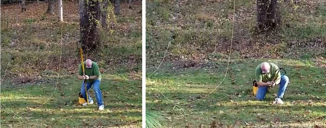
I was trying for maximum height on this launch, so I moved the trigger assembly down on the shaft of the launcher a bit more than usual. It took serious effort to cock the launcher. Note, I am wearing eye protection and pointing the device away from my body.

Launching the line

Bigshot Slingshot
Move to launch position

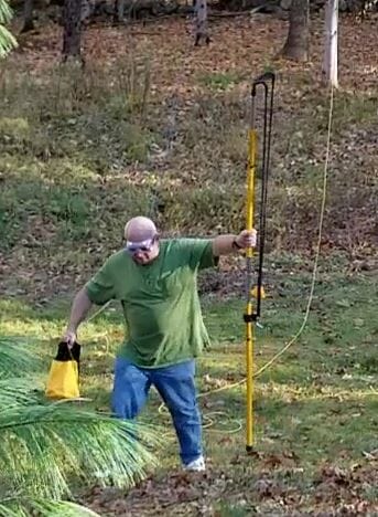
First, you must untangle the throw line before launch. Carefully coil it into the throw bag so it will come out smoothly. The launch should be almost vertical to be able to get the maximum height out of it. Launching at 45 degrees or 60 degrees gets a long distance, but disappointing height. As a result, I think I was launching at 75 or 80 degrees here.

Launching the line
Launching the line

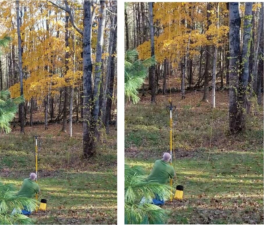
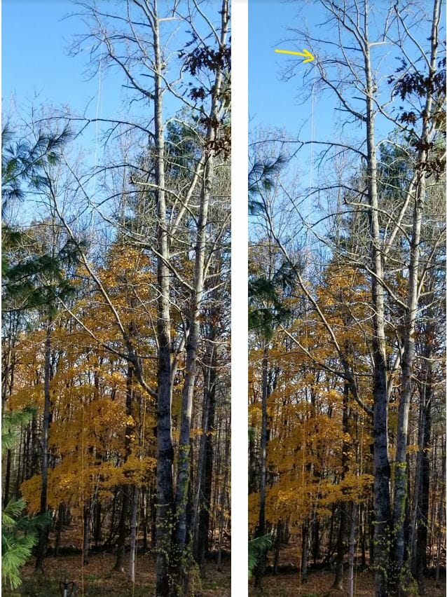
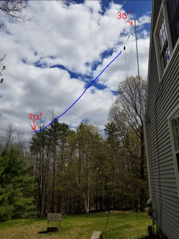
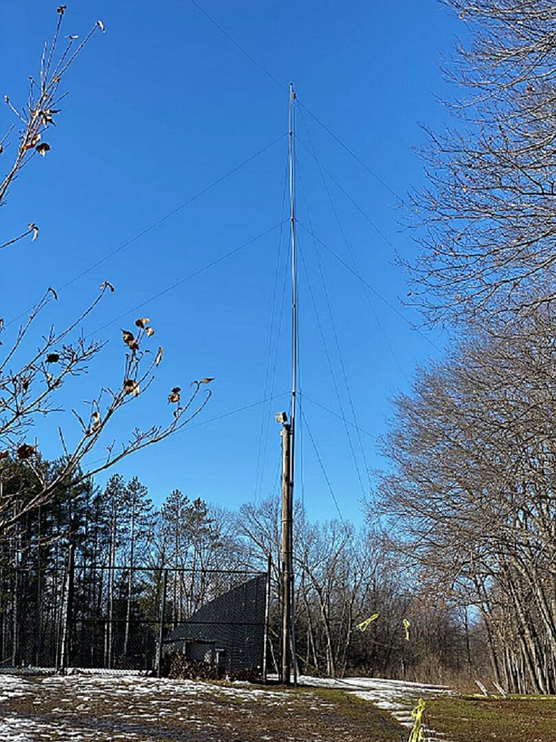
Success, the line is up around 70 feet in the tree

These two pictures fully show the tree to give some scale to how high the end of the antenna is.

Success 70 feet high

This picture, looking South, shows the antenna feed point around 30 feet high at the house. There are three 10-foot chain link fence top rail sections attached to the corner of the house with a line holding the antenna. From there the ground slopes downhill around twenty feet. The end of the 135-foot wire antenna is hung at seventy feet in the tree. It is running North and South with a little bias to the West.

NH QTH EFHW at 70 feet

Did it work?

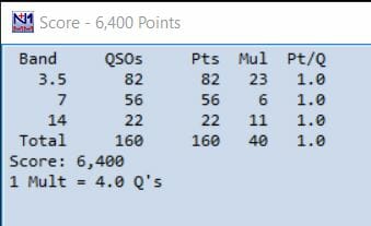
I was eager to find out if it was going to make a noticeable difference in the contest. It did! On the 20 and 40 meter bands I can get through pileups, often on the first or second try. My first QSO on 80 meters was to Ukraine, around 4500 miles away. In the beginning of May, during the NE QSO Party, for instance, I had replies to my CQ on 80 meters with only 100 watts from Italy and Uruguay.  80 meters was my most productive band in the contest.

NEQP 2020 Score Box
NEQP 2020 Score Box

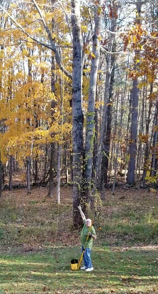
Good for Christmas lights, too!

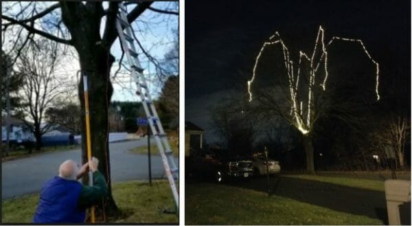
Here is a quick look at the throwline launcher in action. I am sending a line up in a tree to pull up some Christmas lights. Click on the picture to view the video. Each string of lights in the picture on the right represents the arc of the throw-weight and line. The max height in the tree is around 35 feet.

Christmas Lights
Christmas Lights

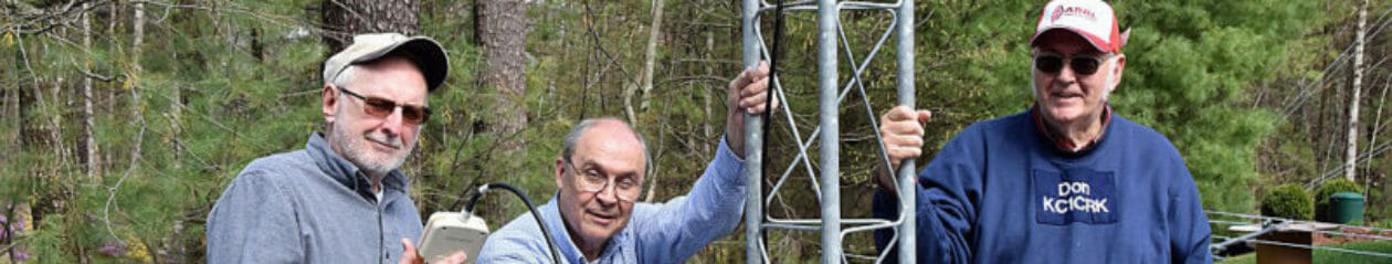
NARS Winter Field Day 2020

During setup for the Nashua Area Radio Society’s 2020 Winter Field Day the spud launcher, we were using broke after setting up a 40-meter delta loop antenna. We still had to set up the 160 Meter Transmit Antenna. It was a dipole, fed at around 50 feet with each end to be installed around 40 feet high. I made a quick trip home to fetch the throwline launcher. Upon my return it was easy to secure the ends of the dipole up in the trees.

Jon, AC1EV

PTT Switch for Remote Operation

When the Nashua Area Radio Society’s Student/Teacher Contest Series was first set up, Fred and Anita (AB1OC/AB1QB)  offered up their station to my son Keith (KC1IMK) and other students that do not have a station at home. Fred and Anita have an amazing station at their QTH and you can find more information on it here.

Then COVID arrived and sharing mikes, headphones, and keyboards at other people’s houses are no longer acceptable.  We cannot risk getting each other sick.  Another way is necessary.  Remote Operation is here!

Fred (AB1OC) and Jamey (AC1DC) worked out the kinks for setting up Remote Operation first.  Then Fred invited Keith and me to try it out. After a couple of hours online with Fred to set up, we were on our own.  Contest Calendar showed the Helvetia Contest that night so we pointed the beams toward Switzerland and called CQ.  Several stations pounced on Keith at once. He worked hard with the mouse, bouncing from the radio PTT button to logging in N1MM.  Once the pile-up was cleared, he pulled off his headset and said “I really wish I had a footswitch like Field Day“.

Remote PTT Switch for SmartSDR

Driven to maintain my “Super-Dad” status, I went to work.  I found a few references at the FlexRadio site:

https://community.flexradio.com/flexradio/topics/physical-ptt-for-remote-smartsdr

https://community.flexradio.com/flexradio/topics/remote-footswitch-how-to-lan-vpn-solution

Looked pretty straight forward to build a Remote PTT Switch.  Configure a SmartSDR CAT interface to monitor hardware flow control pins in a standard serial port. The hard part today is to find a serial port.  They have all been replaced by USB.

There are lots of USB to Serial adapter cables available today for around $20 that should work well. I would recommend one based on the FTDI chip.  Jamie (AC1DC) successfully used a Sabrent USB 2.0 to serial from Amazon:  https://www.amazon.com/gp/product/B07RFNHTL9/ref=ppx_yo_dt_b_asin_title_o02_s00?ie=UTF8&psc=1

I dug out a 15-year-old Belkin adapter from the back of my shack and installed it.  A new Com3 port showed up in Windows 10 device manager.

USB to Serial Adapter for Remote PPT Switch
USB to Serial Adapter

SmartSDR CAT will detect if RTS is shorted to CTS in a Com port.

SerialPinOut

This is a very standardized interface and it was easy to find the pin definition.

Pin 7 is RTS

Pin 8 is CTS.

Easy to spot as they are the center two pins of the row of four.

I also had the mating 9 pin D connector in my bin of parts.  One could probably solder to the pins of the adapter, but I would recommend a connector.  I cut off the 1/4″ plug from a footswitch I bought from Amazon. The two leads were soldered to pins 7 & 8.

https://www.amazon.com/Philmore-LKG-Momentary-Foot-Switch/dp/B004GIIYK0/ref=sr_1_7?dchild=1&keywords=30-17090&qid=1587913482&sr=8-7

Footswitch for Remote PPT Switch

To test it, I downloaded ComTestSerial from Microridge  https://www.microridge.com The test software confirmed the hardware worked.  Each time I pressed and released the footswitch the CTS light in the top right corner changed between Red and Green.

Configuring FlexRadio SmartSDR

Now to configure the software. Open SmartSDR CAT and add a port.  Give it a name.  Set Port Protocol to PTT,  set Port type to Serial, set Serial Port to Existing, and set CAT COM to your new Com port.  Mine was Com3.  Set VFO slice A. Select RTS. Hit save.

SmartSDR Setup for Remote PPT Switch
CAT settings

I found some open spectrum on 20m, crossed fingers, and pressed the switch.

Voila!  It transmitted!

With prolonged use, I found my old adapter was not up to the job.  The drivers were not meant for Windows 10.  It missed about 1 out of 10 switch presses.  I have since upgraded and the new Remote PTT Switch works great.

73, Mark/KC1IML

And here is a link to a more current USB to serial adapter for use in this application. You can learn more about the remote operating setup at AB1OC-AB1QB here.

Fred, AB1OC

A Blast from the Past …

I obtained my FCC Novice license in 1957 at age 13. At that time, I didn’t yet have a station, so I set out to remedy that situation. I had been using a Heathkit AR-3 receiver (4 tube superhet, $29.95 in kit form, cabinet $4.95 extra) I built prior to obtaining my license; while OK for SWLing,  it wasn’t well suited to amateur radio work. My first priority was building a homebrew transmitter while looking for a more suitable but affordable receiver. While I was building the transmitter, my father borrowed a WWII German military receiver from a colleague at work for me to use temporarily. I didn’t know it at the time, but this receiver was a quite sophisticated design. I used this receiver for several months (including for my first ever QSO), but didn’t pay much attention to the details as most of the labeling was in a language I didn’t understand, and I had no manual, other documentation, or knowledgeable guidance.

I recently decided to see if I could more precisely identify this receiver based on my recall of a few unique features of the design.  One very clear recollection is that the frequency display was projected onto a ground glass screen on the front panel.  This turned out to be the definitive clue in identifying this receiver. Another recollection is the strange-looking (to me, at least) vacuum tubes, the bases of some of which could be seen by opening two flip-up covers on the front panel. Using these clues, it was easy, with some internet research,  to zero in on the make and model of the receiver. It was a Tekefunken E52 series manufactured in several variations mainly for the German Luftwaffe between about 1942 and 1945. At the time, I had no understanding of the advanced nature of this design; it was way ahead of its time, and only about 2500 were built. Below are some photos, snippets, and links from the websites I visited. While likely of limited interest to newer hams, in these days of pandemics, lockdowns, and self-isolating, perhaps an interesting diversion. Much more information on the web for those so inclined.

K8EZB Past
Heathkit AR-3
K8EZB Past
Telefunken E52a-1
Telefunken RV12P2000 Vacuum Tube

Telefunken E52 (Koln)

“This is one of the most studied, written about, and discussed receivers in the world”

History:
Empfänger 52 was specified by the Reichsluftfahrtministerium (RLM) in 1939 as one in a series of five similar receivers covering the entire frequency spectrum from LF to UHF, intended for use in the Luftwaffe ground stations, but also for other services and authorities. A request for quotation went out to a few German electronics manufacturers and Telefunken developed and built a prototype of the short wave receiver Köln in the beginning of 1941. Telefunken was chosen to manufacture the series of receivers according to their specification ”Luftboden-Empf.-Programm 2 – 7500 m für die Bodenausrüstung der Deutschen Luftwaffe”, Telefunken Berlin-Zehlendorf  5.5.1941.

Out of four specified receivers E51 Leipzig (LF), E52 Köln (HF), E53 Ulm (VHF), and E54 Kulm (UHF) only Köln was built in large series. In total around 2500 receivers were built from July 1942 to March 1945. The E52 was made in 10 models, of which the E52a-1 (simplified with automatic tuning) and E52b-2 (simplified with manual tuning and unified scale) were the most common. Of all the E52s built there are probably 300 – 500 left, of these perhaps 50 in their original state.

The receiver is modularised, the modules are mounted in a molded aluminum chassis and all connections between the modules are through connectors in a backplane! Both the construction and the performance were far ahead of its time. Only one type of valve, the RV12P2000, was used in the receiver except for the power rectifiers. The intention was that all modules and valves should be interchangeable in the field without the need for realignment. The first test series of around 20 receivers were made in Sachsenwerk in Radeberg from July 1942 of the simplified type E52a-1 and possibly also the type E52b-1. The manufacture was not up to speed until the beginning of 1943. The assembly and alignment were made in Sachsenwerk Niedersedlitz while the modules were made in several different electronics industries.

Receiver data:
The receiver is an advanced single superheterodyne with two RF stages, a mixer/local oscillator, three IF stages, a detector/BFO/AF amplifier, and an output stage for headphones. In total there are 6 tuned circuits in the RF/mixer/oscillator part and the receiver has very high sensitivity and selectivity. The IF stages have a 6-circuit filter plus 4 tunable circuits in a variable crystal filter, the bandwidth is variable from +/- 5 kHz down to +/- 200 Hz @-3dB with very steep slopes, damping 100 times at +/- 10 kHz in wide. The tuning has a coarse scale and a fine-scale projected from a micro photo disc with very high resolution and accuracy. The oscillator has very accurate temperature compensation and thus high stability. Frequency coverage is 1.5 to 25 Mhz in five bands, the sensitivity for AM 3 – 5 uV, CW wide 1.0 uV, and CW narrow 0.3 uV for 5 V output. Mirror frequency damping is at least 50000 and the IF damping is better than 100000 at 1.5 MHz. The stability is better than 30x 10E-6/degree C, which is 30 Hz/MHz/degree C for a freerunning oscillator! Even today this is competitive against many modern receivers comparing sensitivity, selectivity, and stability.

Link: https://kriegsfunker.com/radios/E52_b2.html

Rick, K8EZB

Radio Amateurs Developing Skills Worldwide