Articles and other information related to On The Air Operations, Special Events, Activations, DXxpeditions, Portable and Mobile On The Air Activities, Nets, etc.
A 12-man team will be active from Niger as 5U5R between March 9-21, 2017. QRV on 6 to 160 meters; CW, SSB and RTTY with at least 4 stations on the air simultaneously. Full details here
DX World DXpedition Calendar for March
Like to chase DX? There is quite a bit of good DX on the air this week. I just worked 5U5R from Niger, which was an ATNO (All Time New One) for me! 9N7EI from Nepal and TU7C from Cote D’Ivoire are also on the air.
The DX World website has a calendar for the month which shows all of the DXpeditions for the month. It also has announcements for upcoming DXpeditions.
Fortunately, the Nashua Area Radio Club had a Technician License class coming up and we thought that the new station test would be a great way for our students to learn about Amateur Radio Satellites.
Satellite Status from AMSAT Website
Final preparations included checking the operational status of potential satellites on the AMSAT website. The page shown above is like a spotting cluster for LEO Satellites – it shows satellite activity as reported by HAM satellite operators. Using this information, we configured MacDoppler to track the active satellites.
Satellite Pass Predictions
Next, we used MacDoppler to generate pass predicts for the weekend of our Technical Class. We assembled this data for all of the potential satellites and color-coded the available passes to identify those which had the best chance of producing contacts.
With this done, we loaded our portable tower, antennas, and all of the rest of the gear into our pickup truck and transported it to the class site.
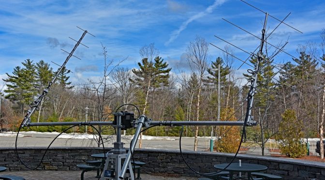
Satellite Antennas Setup Portable
The first step at the class site was to unload all of our gear and move the portable tower to a suitable location. We used a compass to orient the tower to true north and leveled it. We used the weight bags that we made up to anchor the tower securely and then installed the antennas, rotator loops, and control cables. The antenna system worked out very well in the portable environment and was easy to set up.
Satellite Antenna Details
Here’s a closer to look at the LMR-400 UF coax cables which connect the antennas to the rest of the system. The loops just behind the antennas are necessary to keep the coax from affecting the pattern of the antennas. The coax cables shown were made long enough to allow the antennas to be rotated through their full travel in the azimuth and elevation directions without binding.
Satellite Station Portable – Radio and Supporting Equipment
The final step in the portable setup was to put the IC-9100 Transceiver and Supporting Equipment together in the building and check everything out. As soon as we got everything hooked up and working, we heard an ON4 station through FO-29 which was near the end of a low angle pass. A very good sign!
We took some time to fine-tune the calibration of our rotators and to check the operation of the computer controls – everything checked out fine. The video above shows MacDoppler controlling the Azimuth/Elevation rotator and the IC-9100 Transceiver during the testing.
First Contact using New 2.0 Station (via AO-85)
With all the setup done, it was time to try to make our first contact. Fortunately, we did not have long to wait. We caught a medium angle pass of AO-85, a U/V Mode FM Easy Sat. With MacDoppler setup and tracking, we immediately heard contacts being made through AO-85. I gave a whistle and adjusted my uplink VFO until I heard my signal coming back through AO-85. I gave a quick CQ call and immediately got a response from Jonathan, NS4L in Virginia, USA! It took on a few seconds to exchange call signs and grid squares and our first contract with our new station was in the log.
Explaining Satellite System to License Class
Our Technician License Class students were very interested in the station. We spent some time explaining the setup and demonstrating how it worked. We made more contacts between our class sessions using AO-85 and FO-29 (a V/U Mode Linear Transponder Satellite). Our most interesting contact was with Burt, FG8OJ in Guadeloupe through FO-29. It was great to work DX using the new station during the first time we used it.
We learned several things during our first use of the new station. First, while the 35 ft. maximum separation allowed between the antenna system and the rest of the station is adequate in many applications, the antenna system’s close proximity to the building we were in blocked passes to the west of us with this separation. We have subsequently made up an additional set of feed lines using a pair of 100 ft. long 7/8″ hardline coax cables to allow for a greater separation in portable deployments such as this one.
We were glad that we had the Heil Pro 7 Headset with us and we used it for most of our contacts. The separate speaker allowed our students to hear the contacts well and the boom microphone on the Pro 7 Headset eliminated feedback due to our own voice coming back through the satellites. We improvised a mono to stereo converter cable to connect the Heil Pro 7 Headset to one of the two speaker outputs on the IC-9100 Transceiver. This allowed the radio to drive the separate speaker and the headphones at the same time.
We were glad to have the low-noise preamps available. These were especially useful during low-angle satellite passes and the sequencing setup that we built worked well.
All in all, our first test of our new 2.0 Portable Satellite station was a success. Our license classes students enjoyed learning about Amateur Satellites and had fun along with us making contacts through a few of them. Our next goal will be to get packet modes and APRS working with our setup. We plan to do another article in this series when this part of our project is completed. Other articles in this series include:
We are planning to add larger antennas and switchable polarity to our portable satellite station in the near future. This will enable us to make contacts with Satellites and the ISS in more difficult conditions.
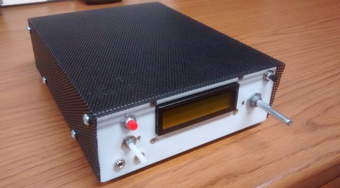
Below is a photo of my BitX-40 kit from Ashhar Farhan VU2ESE in India with my very own custom designed case. The kits are available from http://www.hfsigs.com/
The top cover shown is powder coated steel mesh.
The sheet metal housing was designed in a solid modeling software package called Onshape. This web based software is free to use if your designs are to be available to anyone who signs into an account. This design is “in the cloud” and considered “open hardware”, available to anyone who would like to use it. Below is a screen capture of my Linux desktop running Onshape within a web browser.
With access to a CNC punch press and a 90-ton brake press, a coworker of mine helped out with a bit of “government work”!
I left out some of the detail in the housing to let others enjoy the use of a drill and allow for some creativity with a customized placement of components.
Some of the wires are not needed but may be useful in future “hacks”. The image below shows some of the wires removed from the “Molex” connector. A small sharp object can be used to push in on the barb to remove the contact for a future project.
I used my sketch to drive the LCD screen and the SI5351 chip using the Adafruit library. The checkered block moves left and right between the arrows to indicate when I am at or near the end of travel with the tuning potentiometer.
Stationary
When I move the block all the way to the right with the potentiometer it turns into an arrow and automatically increases the frequency. To make it stop just turn the potentiometer to the left.
Frequency rising
I like the ability to scan the band without having to turn a knob!
Below is an image showing 12v and 24v voltage regulators and electrical tape on the housing tabs. 12v is for the majority of the wiring and I used 24v for the IRF510 PA. The black tape looks nice behind the black mesh cover. while testing I measured about 4W RF output with 12v feeding the PA and 16W RF at 24v.
The bottom has extruded “feet” along with stick on feet to keep the rig from sliding.
I used an SO-239 connector for the antenna. I saved the BNC connector from the kit for test gear. The red terminal post is connected to 32v from a repurposed HP printer power supply. The barrel jack is connected to 16v from the same supply.
For more information on the case, you may contact me through my QRZ page.
We use cookies to ensure that we give you the best experience on our website. If you continue to use this site we will assume that you are happy with it.


")