Category Archives: Newsletter

Nashua Area Radio Society Newsletter Articles. You can find an archive of our Newsletters on our website.

Dayton Hamvention 2016

Fred, AB1OC and I just returned from the 2016 Hamvention in Dayton, OH.

Our first day in Dayton was spent at Contest University – this was our 5th year in attendance but each year we learn more from the contesting experts. This year, we attended two presentations from Frank Donovan, W3LPL on operating techniques for the declining solar cycle and on 80m and 160m antennas.   We also heard a talk from Val NV9L from Ham Nation on Log Analysis tools and another session on SO2R (Single Operator 2 Radio) Operating.
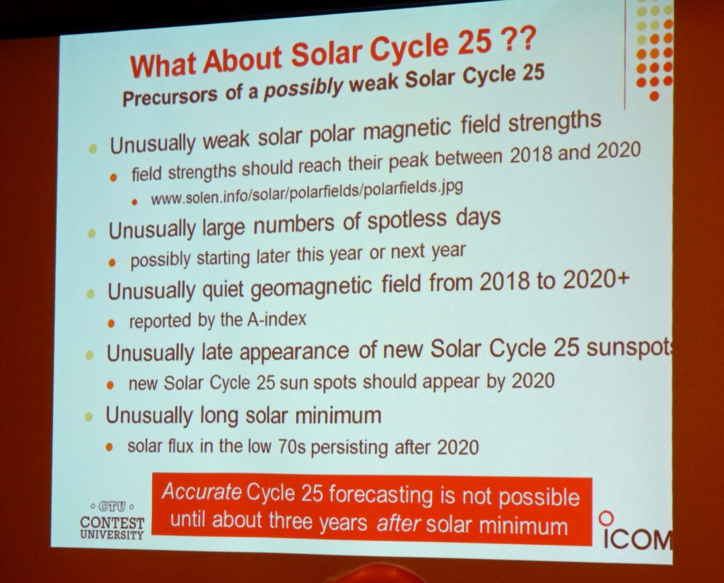
Slide from W3LPL Contest University Presentation

Friday was the first day of the Hamvention and we spent most of the day visiting all the vendor exhibits.   We visited the Icom booth, where we looked at the new Icom 7851. It has an incredible display as well as one of the best receivers on the market.
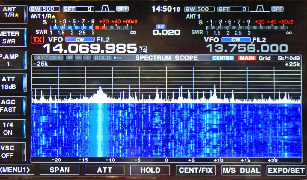
Icom 7851 Display on Large Screen TV

We also saw the new KX2 Transceiver at the Elecraft booth. It is even smaller than the KX3 and is perfect for SOTA and other portable operations. I would expect to hear some NPOTA activations using this radio.
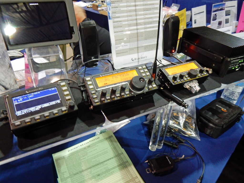
Elecraft KX2 on right, next to a KX3

Friday evening was the Top Band dinner where we learned all about “Top Band Disease” from Larry “Tree” Tyree N6TR.   Hams with this disease are nocturnal, love the bottom of the sunspot cycle. They are constantly improving their 160m antennas – when you upgrade your receive antenna, then there are people who can’t hear you, so then you need to improve your transmit antenna – and the cycle continues…  The DX Alarm Clock is perfect for those with Top Band Disease!

Top Band Dinner Presentation

After the dinner, we were treated to a concert from the Spurious Emissions Band (N0AX, KX9X, K4RO, W4PA), with hits like “On The Cover of the NCJ” and “Sittin on the Edge of the Band”. They were so funny! You can watch their performances on YouTube http://bit.ly/DaytonSpurs2016.
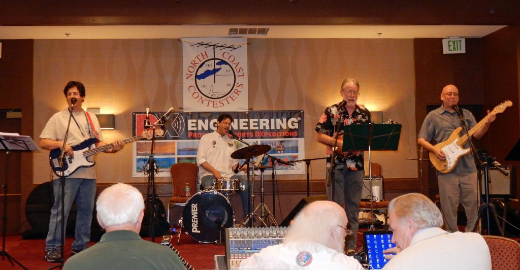
The Spurious Emissions Band
The Spurious Emissions Band Performs at Dayton

On Saturday, Fred, AB1OC and I presented our Station Building talk to around 250 people as part of the Dayton Contest Forum. It was a great honor to be selected to speak there by Doug Grant K1DG, who has organized the Contest Forum for many years.

Fred, AB1OC, Speaks at the Dayton Contest Forum

We also continued to tour the vendor booths, visiting Club Member Bill Barber, NE1B, at the DMR-MARC booth.
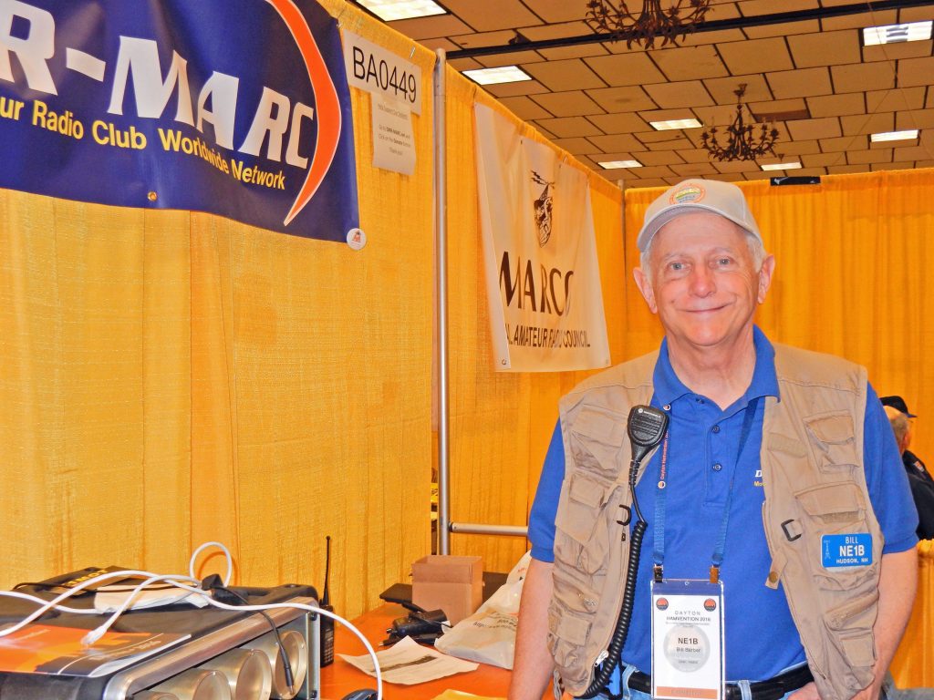
Bill Barber, NE1B at the DMR-MARC Booth

After that, we stopped by Gordon West’s Ham Instructor booth where we spoke to him about the success of the Club’s License classes.  Here is a picture of Gordon, WB6NOA, and Fred sharing the secrets of how the Hilbert Transform and the Flux Capacitor make Single Sideband and Time Travel Possible.
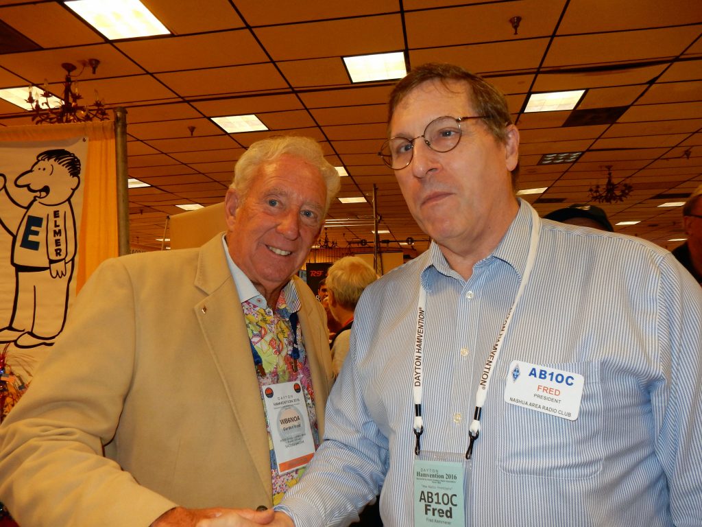
Fred, AB1OC with Gordon West, WB6NOA

We also visited the AMSAT booth, where we met Burns Fisher,  W2BFJ,  who now lives in Brookline, NH and is moving to Hollis.    They had a cube sat on display – you can see how small it is below.  It’s amazing that AMSAT builds and arranges to launch them into orbit so that we can make QSOs through them!
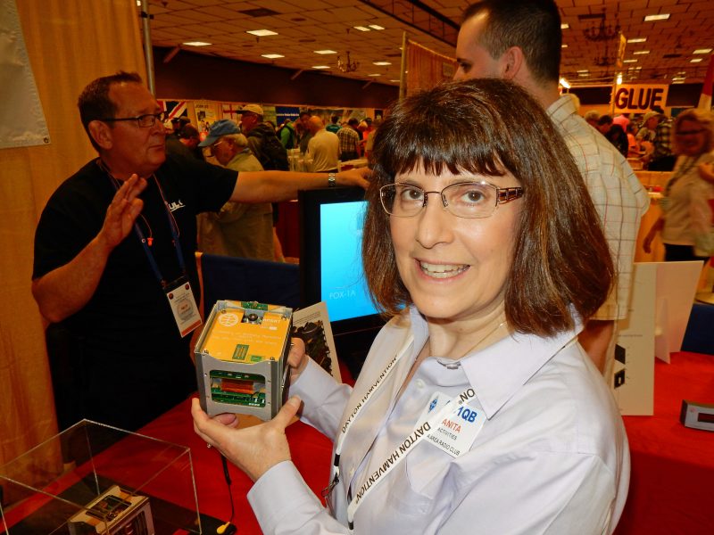
Anita, AB1QB with a Cube Sat

Fred could not resist a visit to Begali Keys where we purchased a neat travel key. It should be great for operating mobile and for Field Day.
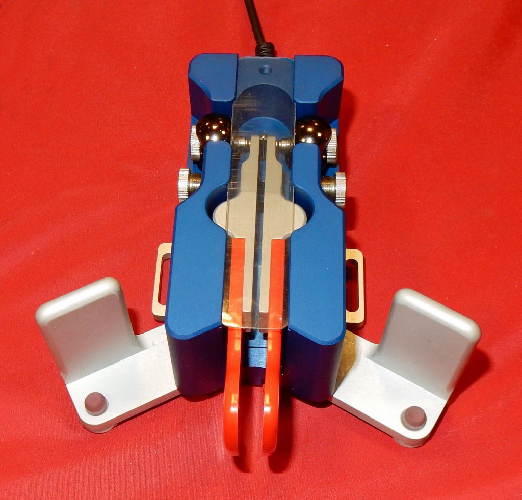
Begali Travel Key
Begali Travel Key

On Sunday, we headed back to New Hampshire, sad that the weekend had come to an end but full of great memories from the trip.

Anita, AB1QB

Plans for N1FD Field Day 2016

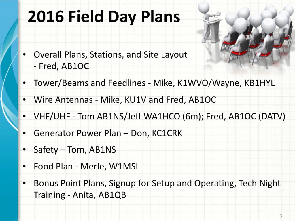
Field Day Planning Team

Our 2016 Field Day Operation is rapidly approaching and our planning is in high gear! We have a great planning team working on Field Day this year and we have a lot of fun planned!

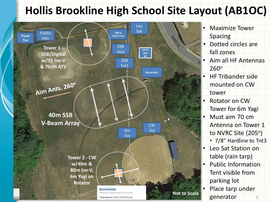
Field Day Planning - Site Layout at Hollis-Brookline High School
Site Layout at Hollis-Brookline High School

We will be operating at the Hollis-Brookline High School in Hollis, NH this year. We’ve been working on antenna plans and a layout for the site. We expect to be 7A or 8A this year. We are also going to try operating using a combination of Digital and SSB Phone from the SSB Stations.

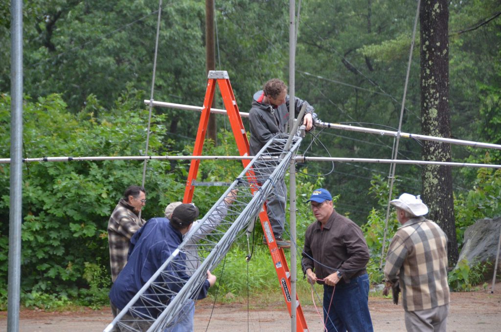
Falling Derrick Tower and Beams

We will have two towers with Tri-band Yagis for 20m, 15m and 10m and Inverted-V antennas for 80m/75m. We will be using triplexers and bandpass filters to allow the Tri-band Yagis to be shared across three transceivers as we did last year.

One tower will be used for CW operations as well as supporting the club’s 4 Element, 6m Yagi. The 6m Yagi will be rotatable. Jeff, WA1HCO and Tom, AB1NS have some cool plans for the 6m station this year which include Meteor Scatter and Es Contacts if we can catch openings on 6m. The CW tower will also have a 40m Inverted-V Antenna.

The other tower will be used to support the SSB/Digital stations on 75m, 20m, 15m, and 10m as well as an 11 Element Yagi for 70cm (more on this below).

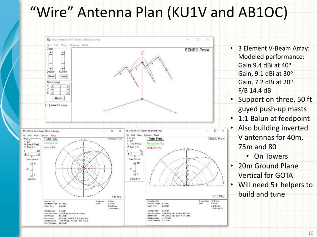
Field Day Planning - 40m 3 Element V-Beam
40m 3 Element V-Beam Plans

We are planning some new antenna and station projects for our 2016 Field Day operation. We are going to build a 3 Element, 40m V-Beam Array using three 50 ft guyed masts. This antenna should perform comparably to a 40m short 2 Element Yagi at 70 ft.

Digital ATV Demonstration on 70cm

We are also planning a Digital Fast Scan ATV link between our Field Day site and the Nashoba Valley Club’s site. This will allow us to send and receive Live Digital Video between the two sites on the 70cm band.

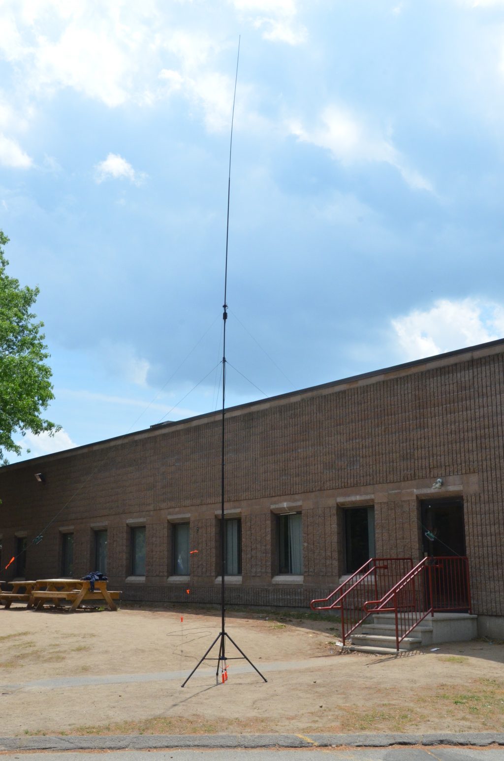
20m Buddipole Ground Plane Antenna for GOTA Station

Wayne, KB1HYL will be operating the GOTA Station again this year. We are going to put the GOTA station on 20m using a Ground Plane Vertical Antenna built from Buddipole Kit.

Club Meeting About Field Day Planning
Club Meeting About Field Day

Our Field Day Planning team is planning a great presentation on Field Day 2016 at our next Club Meeting on June 7th and our Tech Night on June 14th will be all about the Technical Side of Field Day – Building Antennas, Setting Towers and Stations, Loggers, Digital Modes and much more. Don’t miss these!

QRZ  Number  1  Field  Day ?

Fred (Field Day Incident Commander, N1FD)

Hashtags: #ARRL 

A Stealth Antenna Farm

Living in a community that expressly prohibits ham radio towers often means enduring constant frustration trying to work DX with wire antennas or a multi-band vertical with what is always an inadequate radial field (read: less than 200 radials) over the “worse soil in the world”. My mantra of “work ’em on all bands and all modes” that I pursued for many years from my NH QTH has morphed to “hope I can hear them and they can hear me”. My lot can support a 40-foot tower that would be great for a small beam like the Cycle 24 used during the World Radiosport Team Championship a couple of years ago. Unfortunately, I would never get past a permit for the tower base if I ever tried to put one up.

Ah, but there is hope. The frustrations wrought by CC&R limitations often bring out the ingenuity in hams. Thanks to Layne, AE1N, I visited the website of Jeff, AC0C (see AC0C.com). Jeff lived in a condo with the no-tower restrictions. He looked over the attic where he lived and set about figuring out how to build an array of beams using the roof support structure. In a triangular volume measuring 16 feet at the apex, 20 feet long, and 40 feet wide, he managed to cram in a 22-element array that covers 160 – 6 meters! A scan of Jeff’s website is a testament to a ham’s perseverance to build an antenna farm where common sense says you cannot. Jeff used the popular EZNEC modeling program developed and maintained by Roy, W7EL. The overall configuration of the project shown on Jeff’s website looks like the proverbial rat’s nest. Somewhere on his site he mentions using over 1000 feet of coax, hundreds of ferrite cores, dozens of relays, and numerous switching boards to select the desired antenna while holding the RFI beast at bay.

Intrigued by Jeff’s work, I decided to take a look at my garage attic and see what I could do. My attic measures about 17.5 feet long, 19 feet wide, and 5 feet at the center above the floor. There is usable space beyond the garage over the remainder of the house that runs to the back, providing more depth. Unfortunately, my attic runs N-S so that any fixed antenna would have to be situated to favor a pattern to the E/NE direction for DX. I studied Jeff’s design for his 2-element 40 meter Yagi and decided to scale it for 30 meters. Each element resembles an inverted-V with the lower half of the ends bent at right angles to run horizontally along the floor of the attic. The horizontal portions of each element run toward each other so that the antenna resembles a modified “bent” Moxon antenna. (The Moxon antenna owes its design to Les Moxon, G3XN (SK). It is a 2-element beam that resembles a rectangle, is easy to build, and is forgiving in dimensions for a given band.)

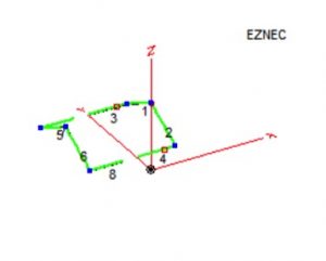
I modeled the antenna with a separation of 19 feet between the elements and inserted loading coils in the driven element to shorten them. The apex height of the antenna is only about 14 feet above the ground so I was not expecting spectacular gain in the primary direction (North). The resulting pattern resembled a low dipole with maximum gain of 4.5 dB North and South, dropping to 3.4 dB at 45 degrees. While this may seem respectable, it occurs for an elevation angle of 45 degrees which means it would not work very well for typical DX angles. Indeed, when I looked at the gain performance at 24 degrees elevation, I had less than a dB. (The astute DX’er will notice that good DX performance occurs for elevation angles of 15 – 20 degrees. When limited to a height of 14 feet, the gain profile at 15 degrees is over 8 dB down from its peak.) Figure 1 shows the layout of the antenna. I realized that I’d be better off with a 30-meter inverted-V dipole off the back of the house.

Stealth Antenna– 30-meter 2-element Attic Yagi
Figure 1 – 30-meter 2-element Attic Yagi

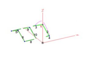
Not to be deterred, I then modeled a 17-meter 2-element beam using relays to disconnect the 30-meter element at its coils and inserting an inverted-V element between the 30-meter elements to act as a director for 17. Figure 2 shows the results where the driven element is on the right and the director is at the center.

Stealth Antenna – 17-meter & 30-meter Attic Yagis
Figure 2 – 17-meter & 30-meter Attic Yagis

The performance for 17 meters was similar to 30 meters with a modified dipole pattern. The gain was a little better at a 24-degree elevation angle but still less than 2 dB. Again, better to stay with my inverted-V that boasts a 3.8 dB gain toward NE.

While I pondered my next move, it occurred to me that what worked for Jeff might not be the best idea for me. All that coax and those ferrite cores pointed to a lot of blood, sweat, and tears to get rid of RFI gremlins that such close quarters tend to foster. I considered using relays to change bands by lengthening or shortening the antenna elements. However, this would mean control cable wires from the shack to the antennas, themselves inadvertent antennas when transmitting. There has to be a better way.

Then, the long-dormant light bulb in my head came on. Why not try a 2-element wire beam? I looked at a model for such a beam for 17 and 15 meters, 2 elements for each band on the same “boom” and each fed separately. The results showed 17 meters behaves as expected with a gain of 6.2 dBi and a F/B of 21.6 dB. However, the 15-meter portion had a peanut-shaped pattern that was reversed from the intended direction with a F/B of less than 5 dB. I adjusted the height of the 15-meter elements within the available limits but to no avail.

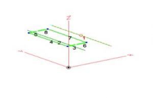
Now what? I looked at the Moxon design again for its space-saving feature to see if I could get more isolation between the beams. I pulled up the file for the 2-element 17-meter beam and another file for a 15-meter Moxon beam. I merged the two antennas and juggled the positions so that the Moxon was a foot above the wire beam. Figure 3 shows the EZNEC model.

Stealth Antenna – 17-meter Beam with 15-meter Moxon Above
Figure 3 – 17-meter Beam with 15-meter Moxon Above

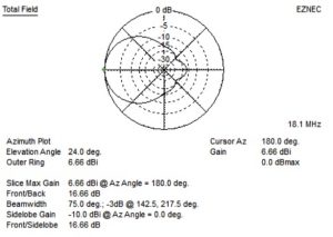
Figure 4 shows the azimuth gain pattern for the 17-meter beam.

Stealth Antenna – 17-meter Beam Pattern (15-meter Moxon Above it)
Figure 4 – 17-meter Beam Pattern (15-meter Moxon Above it)

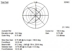
Changing antennas for the 15-meter Moxon antenna produces the pattern shown in Figure 5.

Stealth Antenna – 15-meter Moxon Gain Performance
Figure 5 – 15-meter Moxon Gain Performance

As the model plots suggest, both antennas have nearly identical performance. Success at last! At least on paper minus any interactions and interfering structures such as air conditioning ducts and electrical wiring. Installing two antennas with separate feeds is easy to control with a remote antenna switch. I avoided the need for relays to shorten elements on 17 meters in order to work on 15 meters. I did not want to use relays because of the prospect of RFI causing them to trip, and the need for extra wires from my shack plus ferrite cores for RFI suppression. Now on to the fun part – BUILD IT.

Radio Amateurs Developing Skills Worldwide