In the first RockMite article, I described the receiver of the radio. This article will describe the user interface for the RockMite. The term “user interface” might sound a little fanciful for a radio with almost no controls, but there is plenty to discuss. We should begin with the portion of the schematic dedicated to this function.
A portion of the schematic for the CPU and I/O functions
At the center of the schematic is a PIC processor from MicroChip corporation. These are small 8-bit computers that have dedicated I/O onboard. They are simple to program and are very inexpensive, key features for a radio that must cost under $50. Two of the input lines for the processor (pins 6 and 7) go to a 3.5mm stereo connector for iambic paddle input. Pin 6 connects to the “dash” or “dah” line, and pin 7 connected to the “dot” or “dit” line of the paddle. One of the functions of this PIC microprocessor is to provide the radio with an iambic keyer function.
The other user input is a single button. This button serves multiple purposes. A press of less than a quarter second tells the processor to “shift” the radio’s frequency. More on this in a bit. A longer press (greater than a quarter second) puts the keyer into “speed adjustment mode” that monitors the paddle inputs. Tapping or holding the “dit” side increases keyer speed; tapping or holding the “dah” side decreases keyer speed. Do neither for a second-and-a-half and the processor reverts back to standard iambic keyer mode.
The “shift” mode is the more interesting effects from a button press. The RockMite is actually able to operate on TWO frequencies, not just one. There is a special circuit in with the crystal controlled oscillator that causes this frequency shift. That will be discussed in the next RockMite article. All we need to know for now is that the “shift” line comes out of pin 3 and controls a 2N7000 transistor switch.
The other two outputs of the microprocessor are to the sidetone and the transmit/receive (T/R) switch. The sidetone is the sound you hear when keying. That’s the audio feedback on your paddle operation. The RockMite sends a square wave from this pin to the audio amplifier described in last month’s article. The sound of a square wave in your ears is harsh, and there are a number of mods available to clean this up.
The T/R line controls the mode of the radio. Is it in receive mode or transmit mode? This will be discussed in the article that deals with the transmitter.
This was a brief article but we’re left with two interesting threads to pull on: radio’s oscillator (and shift function), and the radio’s transmitter (and the T/R switch). We’ll start with the oscillator next time.
This Christmas I bought a 28 watt solar panel and MPPT charge controller from Bioenno. I haven’t had much time to use it until recently with the weather getting warmer. I’ve been able to use this with my 7.5 amp hour battery which will power the KX2 for quite some time. I’ve also been watching a lot of videos on YouTube about portable power boxes and I thought it would be nice to have something a little heftier for car camping or portable activations that I wasn’t carry gear very far.
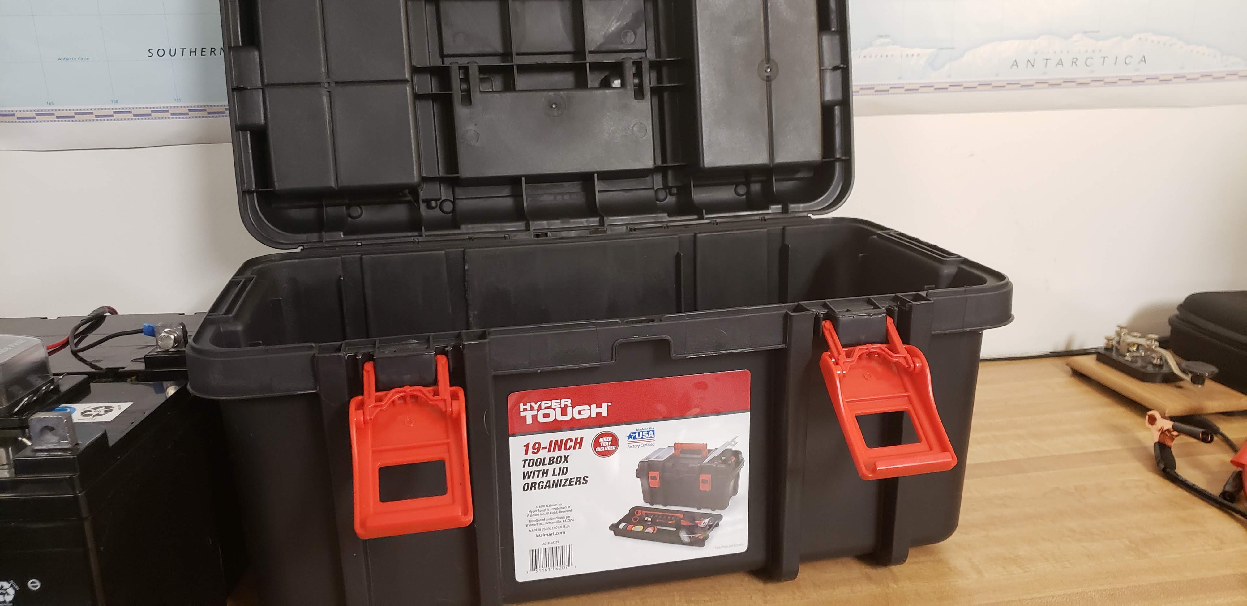
This past week I finally got to work on it. I started with a HyperTough 19 inch tool box from WalMart for the battery box. I have two 12-volt, 35 amp hour AGM batteries from Harbor Freight that fit in the box nicely with a little extra room so that everything can be inside the box.
WalMart Tool Box to be used as the battery box
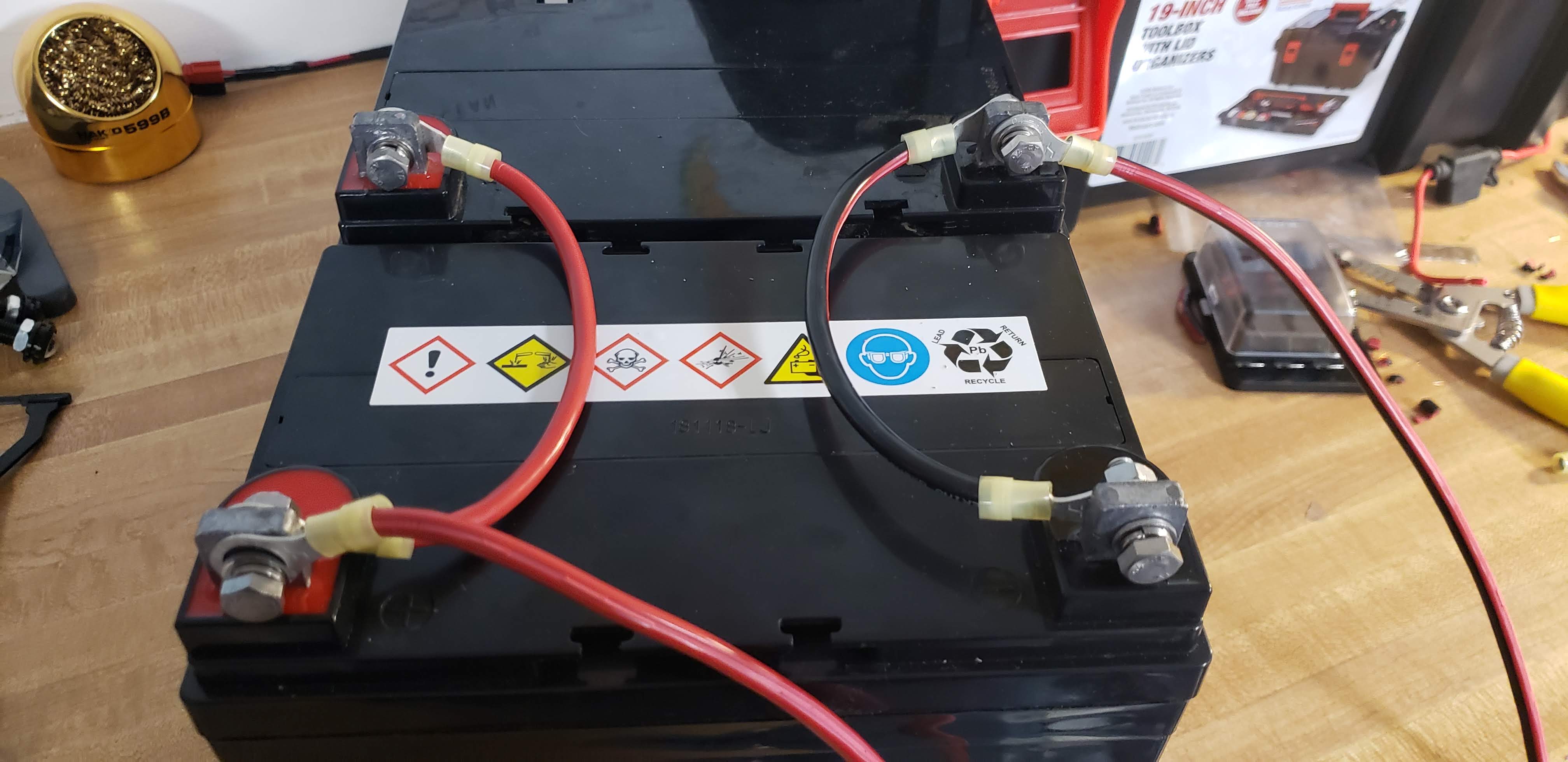
I wired the two batteries in parallel to give me 12-volts and 70 amp hours. I read that the AMG batteries do not emit any hydrogen gas so I did not put any vents in the box (yet).
12 Volt, 35 Amp Hour Batteries wired in parallel (12 volts, 70 Amp Hour)
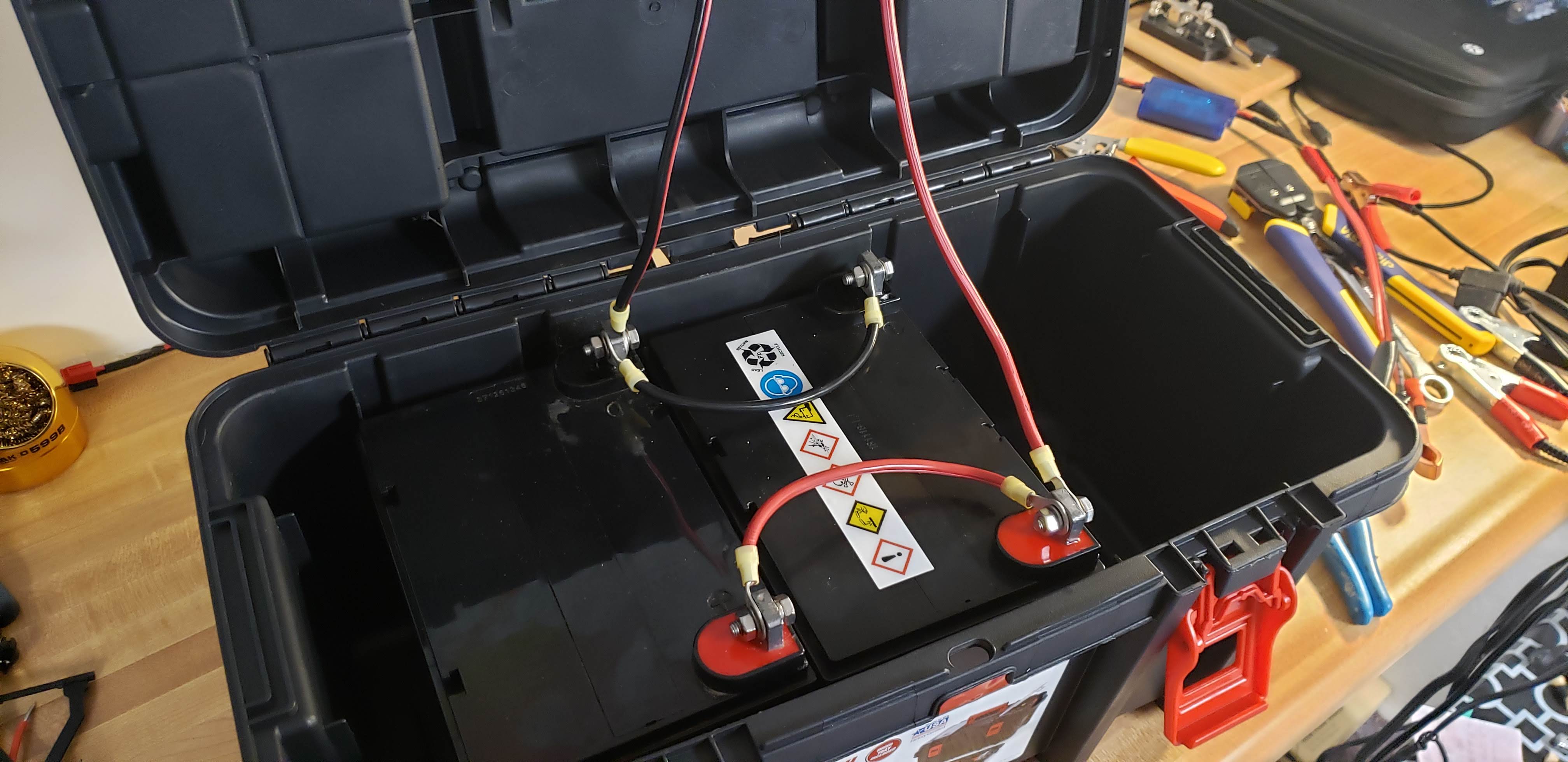
Once the batteries were wired in parallel they fit perfectly in the box! I originally had planned on putting a small computer fan on one end to use as an exhaust and put in venting holes as well, but did not do this after reading more about the AGM batteries.
The batteries fit nicely in the box!
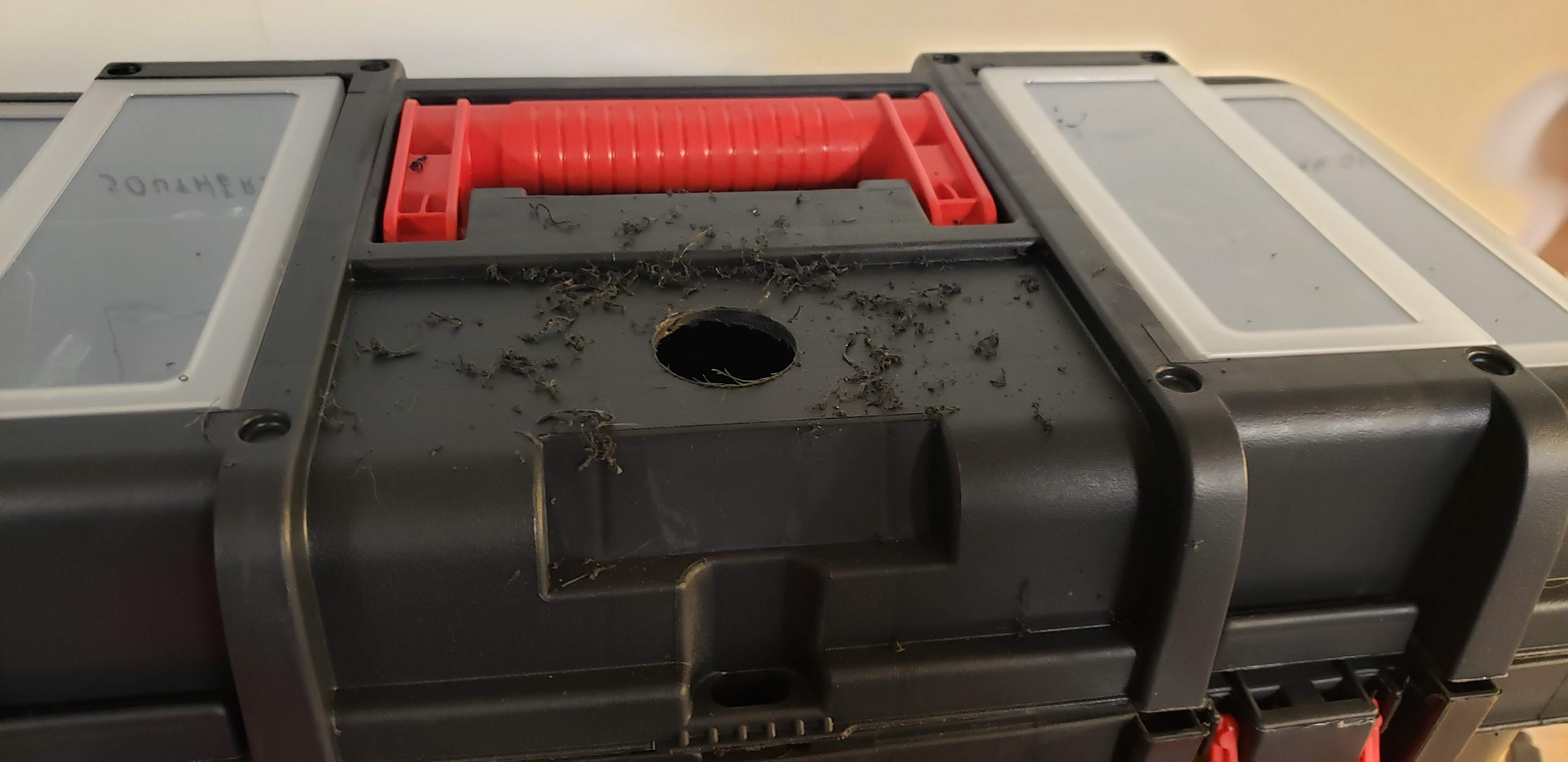
I took ideas from a bunch of different YouTube videos that I watched to try to fit what I wanted for the box. I started laying out where I wanted everything on the box and started drilling holes.
Laying out components
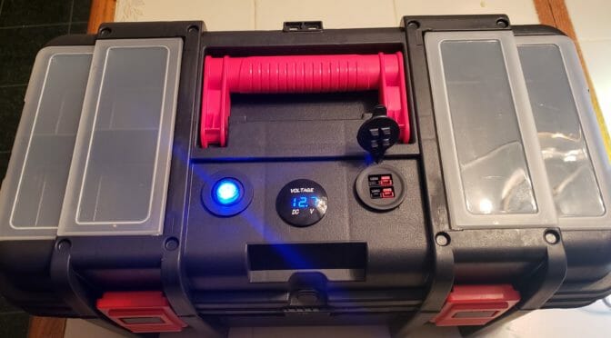
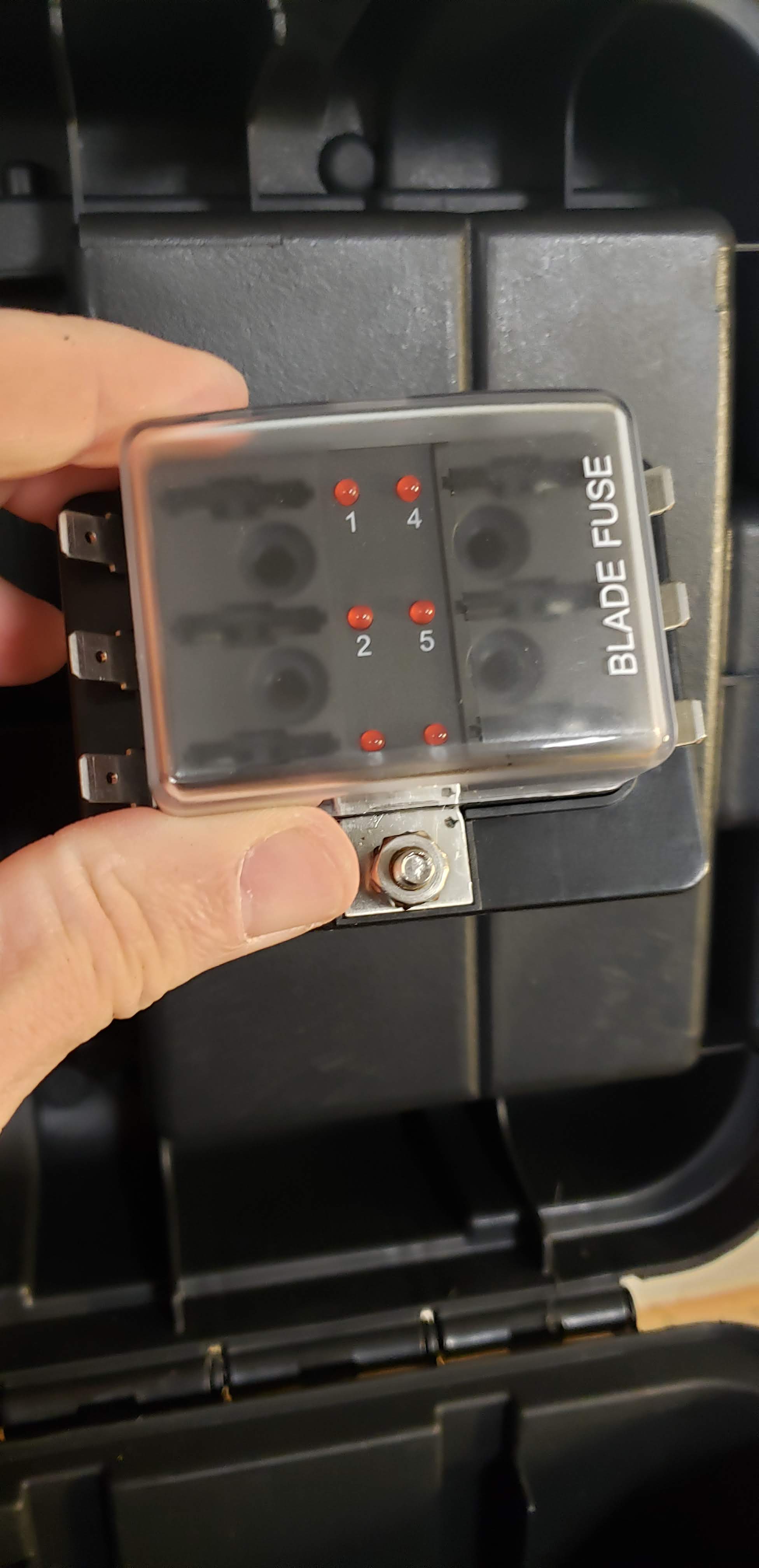
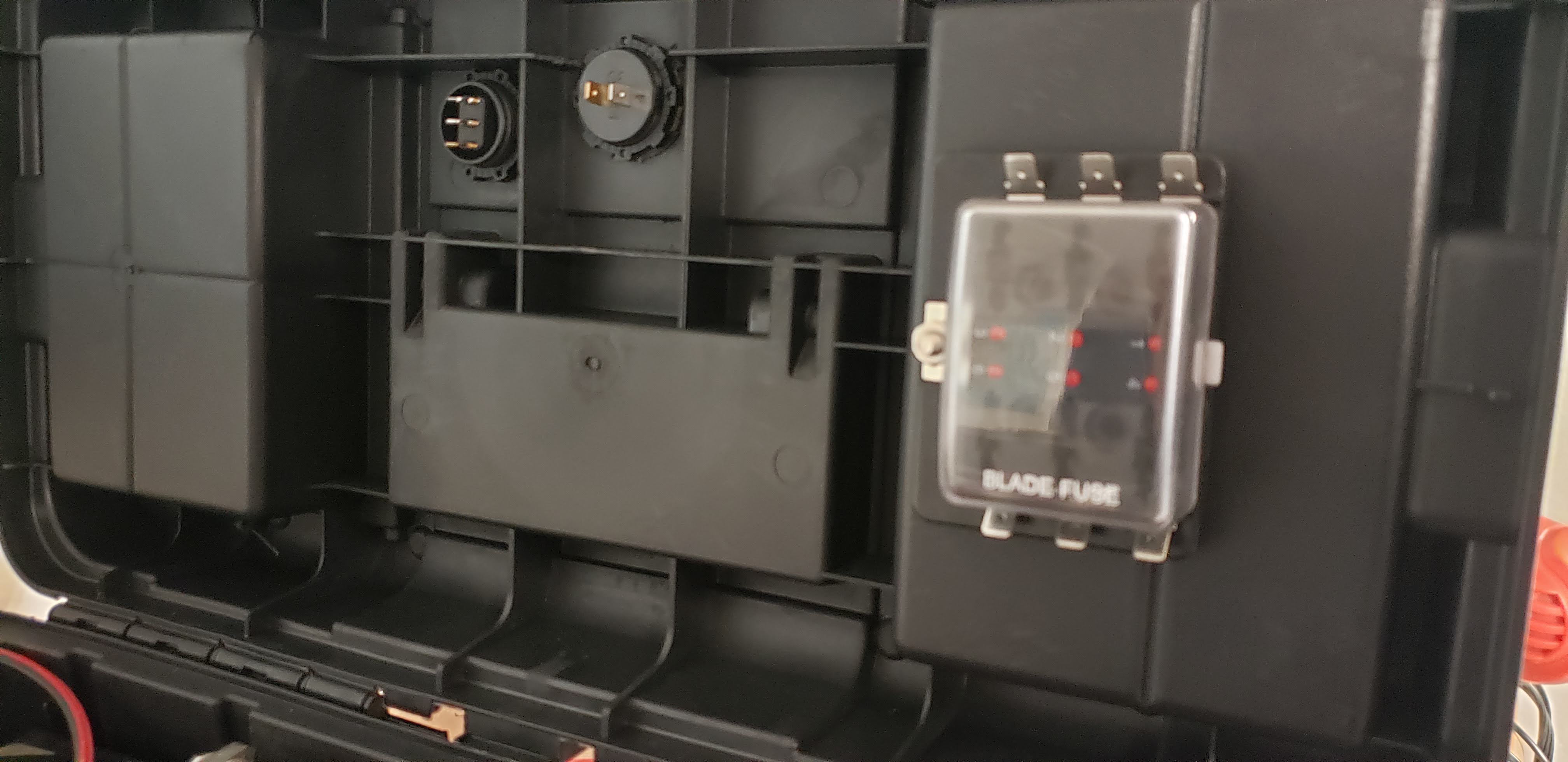
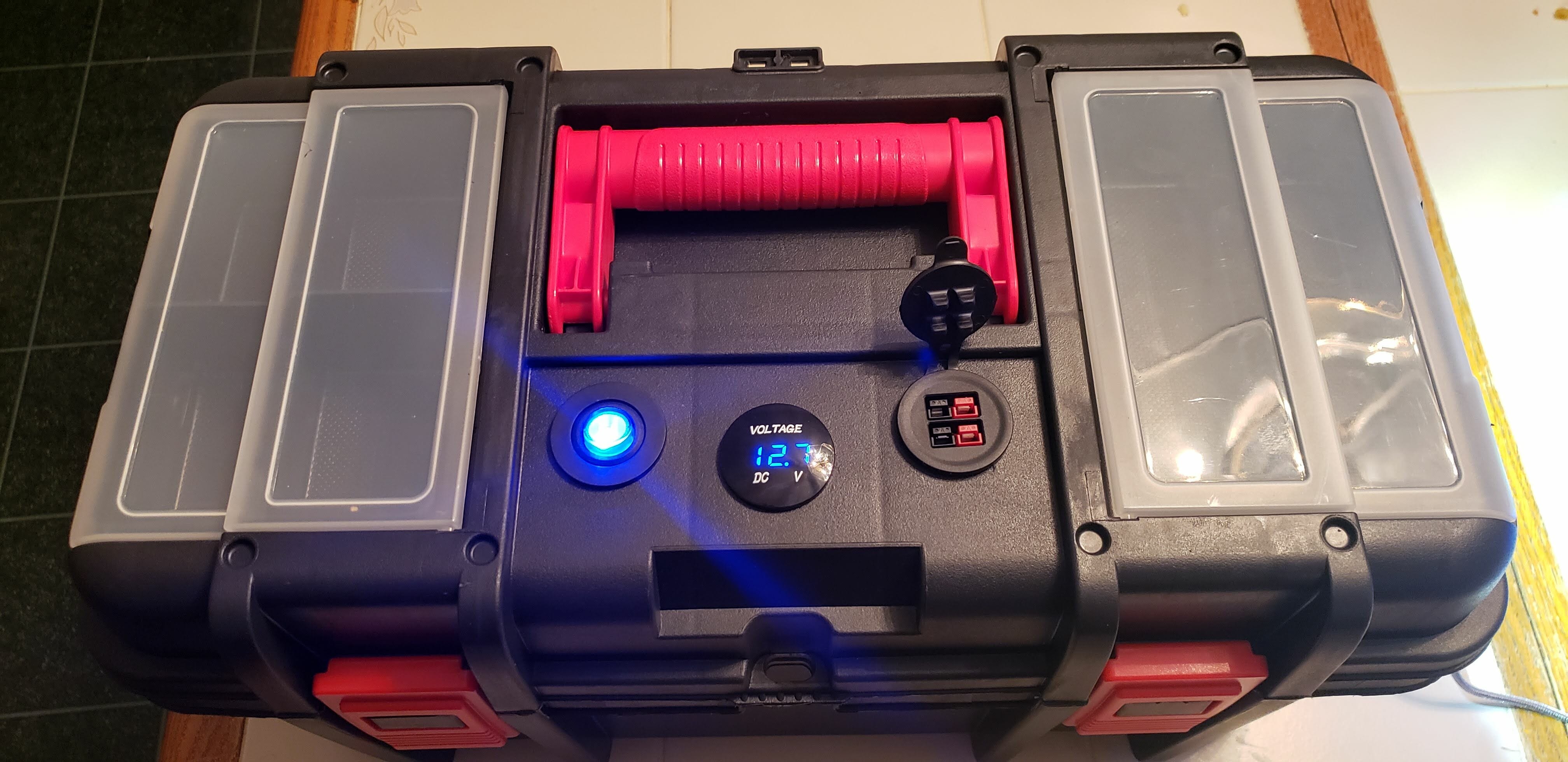
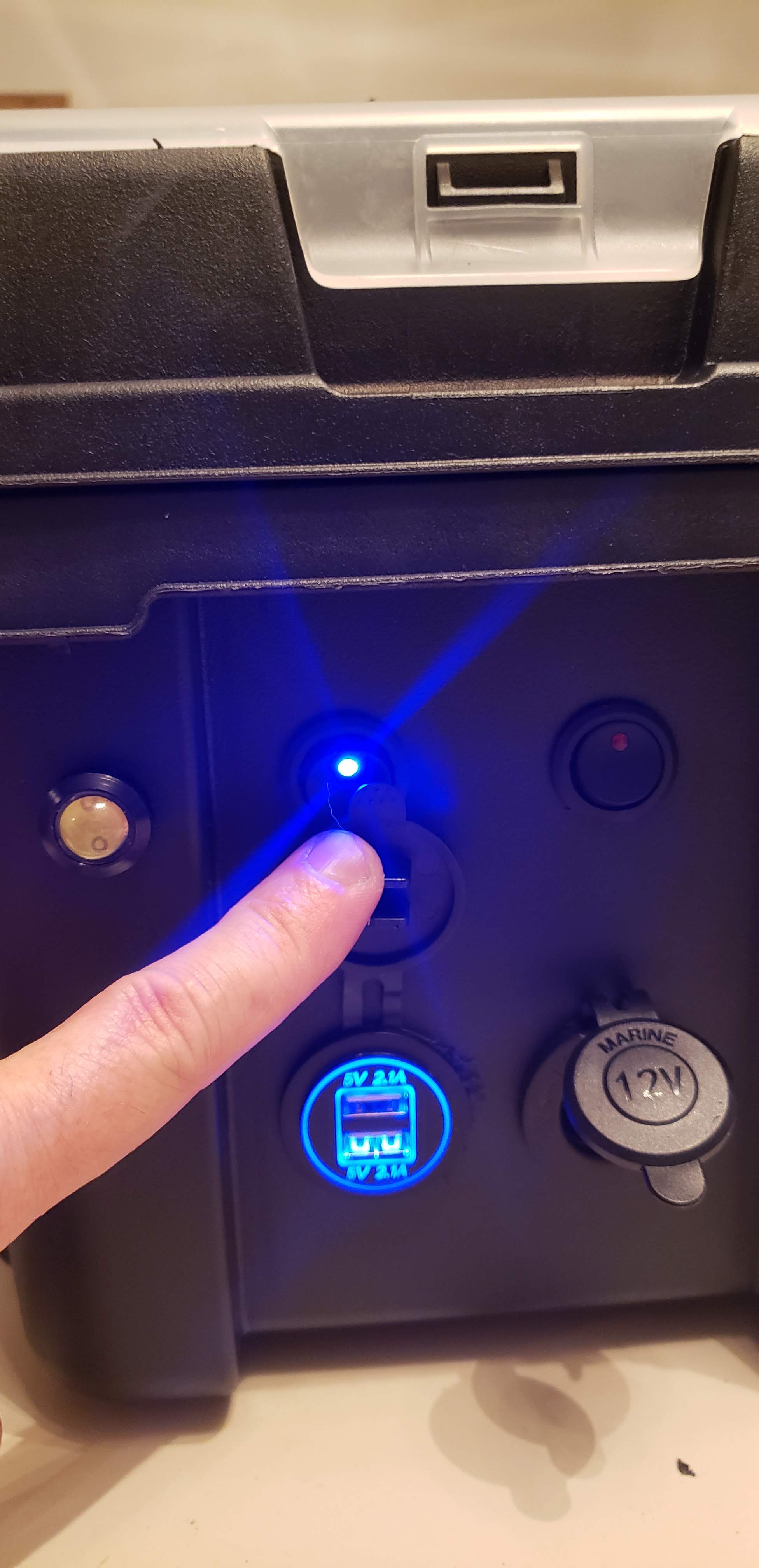
The components I have on the box are a volt meter in the center of the lid along with a master switch for power and a 2 port power pole outlet to plug in a radio. On the front side of the box I have two small switched LED lights, a port with two 2.1 amp USB chargers and a cigarette lighter adapter. All of the power runs through a fuse box. I used Velcro to attach the fuse box to the inside of the lid of the box.
Fuse BoxFuse Box Attached
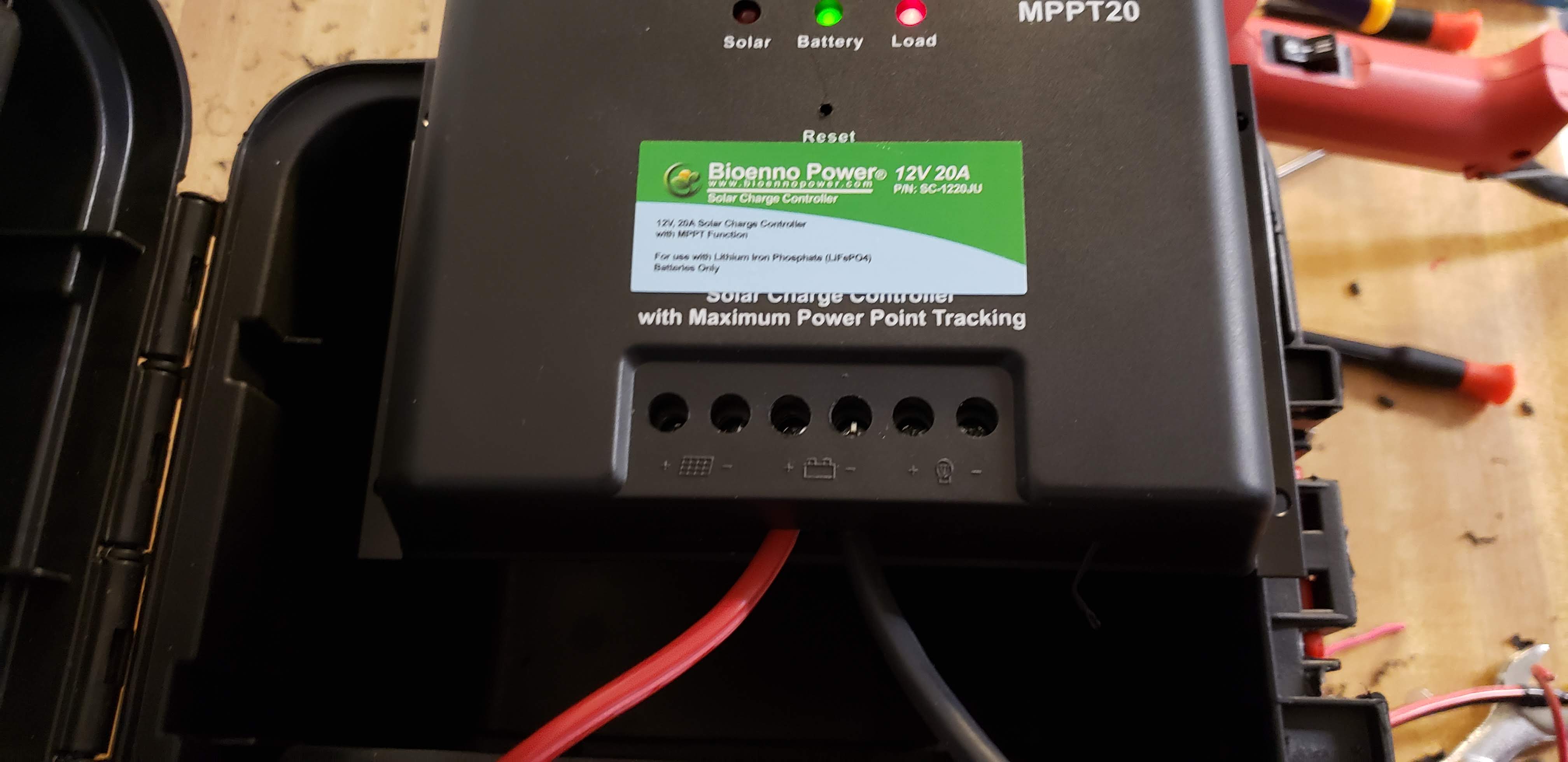
Once all the components were drilled and put in place I put the Bioenno Solar Charge Contoller in the box. I attached this with Velcro to the battery so that I can easily remove it when I want to go out for lighter portable activations.
Solar Charge Controller
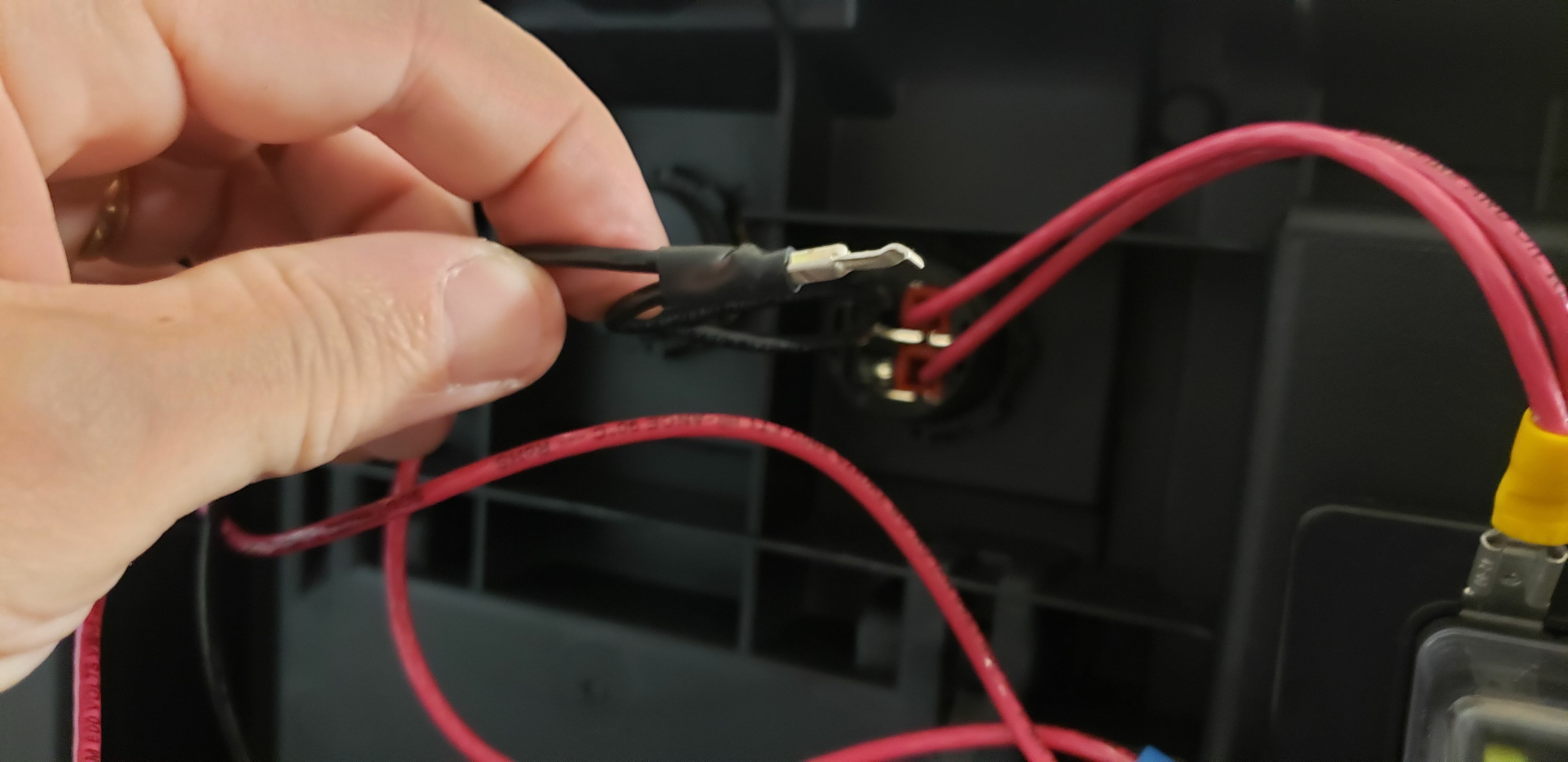
The hardest part was the wiring and it wasn’t really hard, just a little time consuming. I linked all the negatives together with spade connectors and wired all the positives to the fuse box. The power pole connection was probably the most difficult.
Power Pole Connection
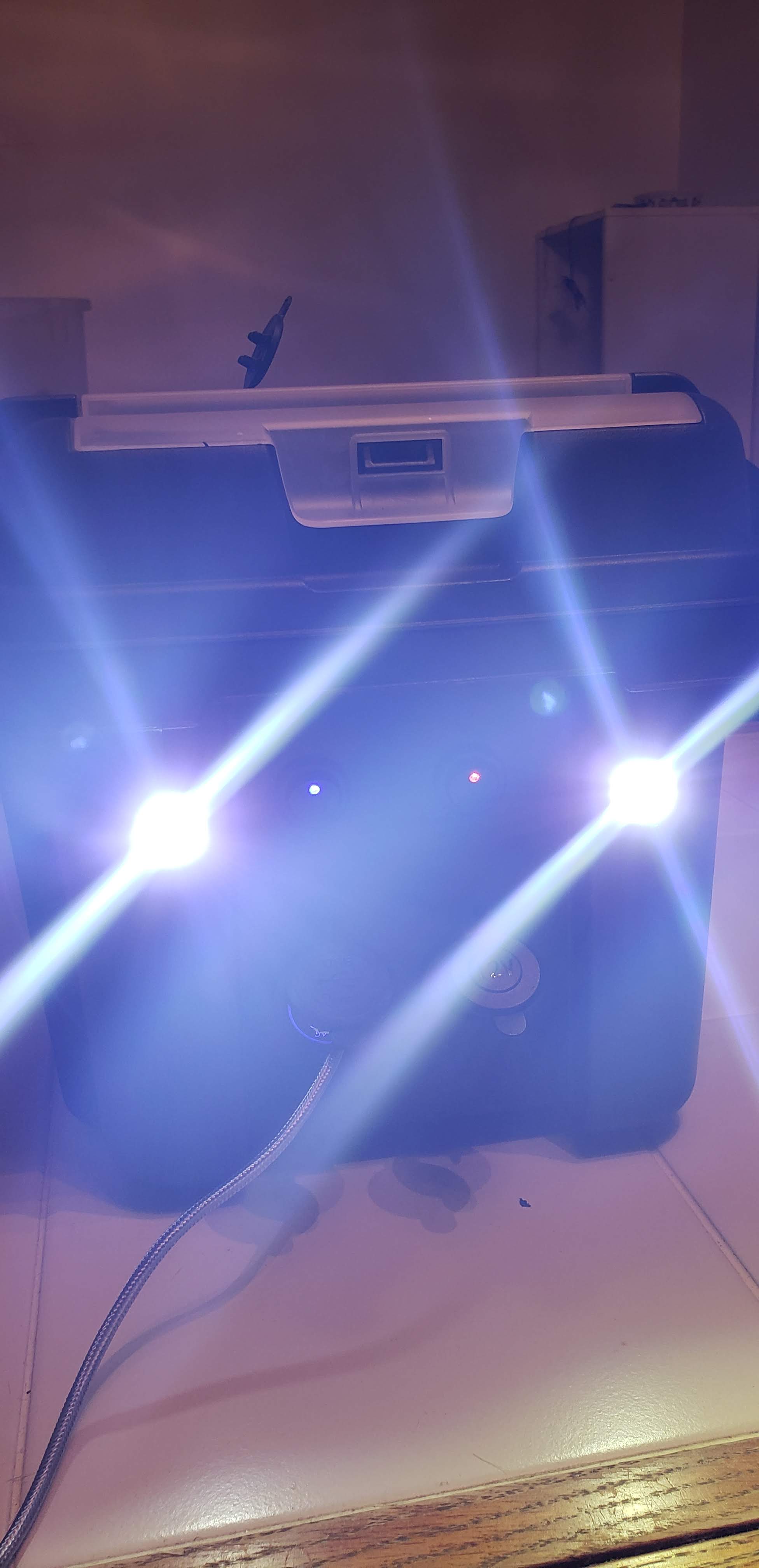
With the wiring complete I quickly tidied it up and tested out all the components and… it worked! I’m very happy with how it came out and can’t wait to get out and do POTA now! Something that’s not showing is the input for the solar charge panel. I’ve got a power pole connector that will attach the solar panel to the solar charge controller. I’d like to get another connector to run through the box. As it is now I have to open the lid to charge the battery. I’m also thinking about adding a strip of LEDs around the edge of the lid for some additional light at night.
Battery Box Completed
Let me know what you think. Any suggestions as to how to make this better are also welcomed!
Front of Batter Box with switched powerBattery Box with LEDs
The little RockMite was designed and sold by Dave Benson, K1SWL, for many years. When Dave retired from the task some time ago he was sure to hand it off to someone he (and we all) could trust to be a good steward for its legacy. That man was Rex, W1REX, proprietor of the amazing QRPme.com website. Under Rex’s steady hand the RockMite has thrived. This article will begin to look at the magic of the RockMite’s design.
What is a RockMite? The RockMite is a crystal controlled QRP transmitter that can operate on one frequency (okay, two frequencies, but we won’t get to that until later). It has a little PIC processor on the board that hosts a CW keyer and provides some feedback (through audio) of the state of the radio. The design is so small that it fits easily into an Altoids tin or other small enclosure. Third party outfits also sold very nice aluminum anodized cases that gave your radio a very finished look.
Close-up view of NE1RD’s 20m RockMite in a blue anodized aluminum case
The schematic for the RockMite is deceptively simple. Here it is (click the image to make it bigger):
Schematic for the RockMite transceiver (from QRPMe.com)
Let’s walk through the signal paths a step-at-a-time to see how the radio works.
The Receiver
The RockMite is a direct conversion receiver. That means that the signal you get off the air is processed directly and converted into audio. Contrast a direct conversion receiver with a superheterodyne receiver that has multiple steps where the original signal is translated into an intermediate frequency, processed further, then the audio is created. Direct conversion receivers are more simple than their “superhet” counterparts, but superhet receivers make it easier to make multi-band radios.
Before we can look at how the signal we receive is turned into audio we need to learn about something that I always thought was amazing. It is astonishing to me how often some obscure mathematical concept has a purpose in our physical world. Here’s the one we need now.
If you have a frequency and “mix” it with another frequency, you get the following from that combination:
You get the original two frequencies back out,
You get the sum of the frequencies,
and you get the difference in the frequencies
Imagine you have a 40m RockMite. You want to be able to listen to signals on that band. How do you convert something at 7,000,000 Hz to something at 600 Hz? You mix signals together!
The SA602/612 or NE602/612 double balanced mixer is a part that does nearly all the heavy lifting. Here is a block diagram of what you have inside this small 8-pin DIP part.
NE612 Mixer block diagram
The interesting bit in this picture is the circle with the cross. This is the mixer part. The other pieces are just there to support the mixer. Note that the mixer has two inputs: one from an oscillator, and the other from an input signal source. The mixer “mixes” those two signals and outputs the result on pins 4 and 5.
The general idea is this: apply power to pins 8 (Vcc) and 3 (ground). Then hang enough parts between pins 6 and 7 to have the internal oscillator create a steady signal. This can be a crystal oscillator, or just a capacitor and inductor network, depending on your needs. Then apply a signal to pins 1 and 2. The results (f1, f2, f1+f2, and f1-f2) appear at pins 4 and 5.
If we configure the oscillator to be, say, 7.040 MHz, then mix in a signal near that frequency from our antenna (say 7.041 MHz), the mixer should create our four products (7.040 MHz, 7.041 MHz, 14.081 MHz, and 0.001 MHz, which is 1 KHz. That frequency is a little high for comfortable audio listening, but it is within the audio range. If only we could snag only that frequency and ignore the others.
We can. We run the results of our mixing through a low-pass filter and we’re left with only frequencies below that filter’s limits. Then again, if we are only doing audio processing those other frequencies become nearly invisible. (Good headphones might respond to 20 Hz to 20 KHz, but a frequency of 7 MHz is going to do nothing!) Let’s look at the mixer part of the receiver in the RockMite.
RockMite Mixer
The direct conversion receiver mixer
The signals come in on the left and go left-to-right. The point (A) on the diagram is a connection to the antenna. That is the source of our CW signal. It travels through a capacitor C1 to AC-couple the signal to the remainder of the mixer. We then have a couple of back-to-back diodes D1 and D2 that are used to clamp the amplitude of the signal received. This protects the rest of the circuit should we get an unusually strong signal from a nearby transmitter or a lightning strike somewhere. Diodes like these “turn on” (conduct) in the forward direction when there is 0.7 Volts present. We hope our radio signals are strong, but not that strong! So, if there is an exceptionally high voltage (RF-wise) then we want the diode to turn on and shunt that signal to ground. In normal operation, those diodes sit there and never turn on.
The signal is then pass through a crystal for this band. The RockMite we are studying is built for a single frequency: 7.040 MHz. By sending the signal through a crystal of this frequency we allow signals of that particular frequency to pass easily while rejecting other signals far from 7.040 MHz. By the time our signal is on the right side of that crystal, it should be a reasonably pure signal near that frequency.[I’m going to ignore the capacitor C2.]
What we have left is the mixer! I said that power comes in through pins 8 (+) and 3 (-). For pin 8 we have a connection to V+ (our power supply) running through a current limiting resistor R1. We also have a connection to ground through a Zener diode. Zener diodes are interesting because they can be used as a very simple voltage regulator. In this case, the diode D3 is a 6.0 Volt Zener. That means that the diode “turns on” when it sees a voltage above 6.0 Volts and maintains a 6.0 Volt potential at its feed. So, if V+ is 6.0 Volts then the diode probably does not even turn on at all. If V+ is 6.1 Volts then the diode turns on just enough to bring the voltage back to 6.0 Volts.
The SA612 Mixer is powered at 6.0 Volts because of the Zener diode. The resistor R1, therefore, is the current limiting resistor to protect the Zener D3. The C101 capacitor is connected to ground just to filter away any spurious noise that is on the power lead going into the mixer.
Pin 3 of the SA612 is connected directly to ground. With these two pins configured, we have successfully powered the device.
Pins 1 and 2 of the SA612 are the input to the device. This is where we send in the signal we want to process. Pin 2 is connected to the signal path and the crystal Y1. Pin 1 is connected to ground (though through an AC coupling). That’s our input for the signal. Now we need to mix it with something.
The Oscillator in the SA612 can be driven with passive parts (like crystals, capacitors, etc.), or it can be driven directly from an external oscillator through pin 6. That’s the decision Dave Benson made when he designed this radio. So, for now, assume that the signal coming in from the outside directed at pin 6 is from an oscillator not pictured. Again, like so many other things here, this is AC coupled through a capacitor (C3 in this case). We now have our baseline frequency.
If the input frequency from point (A) in the diagram is 7.041 MHz, and the oscillator coming in through pin 6 on the SA612 mixer is 7.040 MHz, then we will get the four products we discussed (the original frequencies from our two sources, and the sum and differences of them). That is precisely what is produced in our pins 4 and 5 on the SA612 mixer.
The hard part of the radio is done! We have taken a signal off the air and converted it into something our ears can hear. All we need to do is make it loud enough. To do that we use a single-chip amplifier solution built around the LM1458 Operational Amplifier. (Note that Benson only needed to use one of the two OpAmps on the device. Even with the design this compact he had excess capacity!) Here’s the part of the schematic for the audio amplifier.
The audio amplifier stage for the RockMite, enough power to drive headphones
Here is the block diagram for the LM1458 device.
The LM1458 Dual Operational Amplifier
I’m not going to go through how the audio amplifier works. (I’m not all that hot on good amplifier design!) But, you don’t need to know much here except (1) the output from the mixer drives the amplifier directly. The output of the amplifier is run through a transistor switch Q1, a 2N7000, that can connect, or disconnect, this amplifier from the headphone jack. Why do we need this?
The RockMite is a transceiver. When we are transmitting it is nice to be able to hear a “sidetone” of our keying. When we transmit the switch (Q1) turns off the signal path to the audio amplifier and the “Sidetone” signal (that comes in from another part of the circuit) drives the headphones instead.
What’s next?
This concludes the discussion of the RockMite’s receiver. I’ll continue on with follow-up articles for the radio’s oscillator, the keyer, the transmitter, and final amplifier, and the output filtering starting next month.
We use cookies to ensure that we give you the best experience on our website. If you continue to use this site we will assume that you are happy with it.