Category Archives: Homebrewing

Articles and other information related to Homebrewing, station building, kit building, and other custom Ham Radio projects.

Bigshot Slingshot Throwline Launcher for Raising Wire Antennas

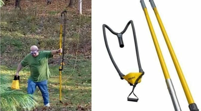
Bigshot Slingshot to launch a line for an antenna

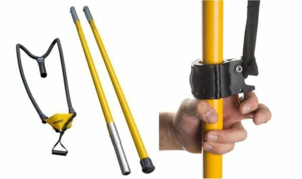
There are several tall trees at my NH QTH and I decided to put an antenna up as high as possible in one of them. I needed a way to accurately put a wire high up into the tree. I read about spud cannons used to launch a line up for an antenna and considered buying or borrowing one for the project. Around this time, I saw a device called a Bigshot Slingshot Throwline Launcher on a TV show about building treehouses and it intrigued me. It is heavy duty and can throw a 10 oz. or 12 oz. weight with a 3/8 inch line attached up 100 feet or more.
Bigshot Slingshot
Bigshot Line Launcher

I found a deluxe kit on Amazon which contained the slingshot and trigger assembly along with spare elastic bands, throw weights, line, line bag, and carrying case. It is built robustly, to commercial standards and I was eager to try it out. I did a few dry runs and learned that it could easily launch the weight 75 feet up. For more height, set the trigger assembly lower on the pole to stretch the elastics more and launch even higher.

Caution!

An Important Word of Caution Here!! This device is powerful and can cause injury if not used carefully. Read all the instructions, wear eye protection, and like a gun, point it away from anything you do not want to break. I am 6’2” and 275 lbs. when cocking the elastics and straining against their pull this device lifted me from the ground and pulled me off balance with ease. I have a lot of respect for the power it has and you should too.

End Fed Half Wave Antenna at 50 Feet

I previously used this line launcher to install a MyAntennas.com 8010 EFHW antenna in my NH QTH backyard with the endpoint up in a tree 50 feet high. I was happy with the performance there for 6 months until I tried working in the CQ SSB DX WW contest. Before the contest, I logged QSOs on 20 and 40 meters all over the US, South America, Africa, and Europe, along with some 80 meter QSOs out to around 1500 miles. However, during the contest, I had difficulty breaking pileups, so I decided to try and raise the tree end of the antenna.

Preparing to launch the line

Bigshot Slingshot
Old rope in the tree

The line hanging from the tree is what held the antenna at 50 feet. I will tie the line to the throw line when I shoot it up to the higher branch.
Cocking the catapult

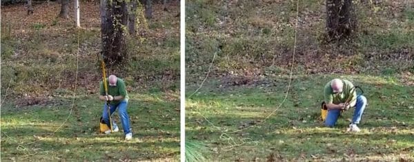
I was trying for maximum height on this launch, so I moved the trigger assembly down on the shaft of the launcher a bit more than usual. It took serious effort to cock the launcher. Note, I am wearing eye protection and pointing the device away from my body.

Launching the line
Bigshot Slingshot
Move to launch position

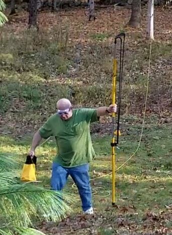
First, you must untangle the throw line before launch. Carefully coil it into the throw bag so it will come out smoothly. The launch should be almost vertical to be able to get the maximum height out of it. Launching at 45 degrees or 60 degrees gets a long distance, but disappointing height. As a result, I think I was launching at 75 or 80 degrees here.
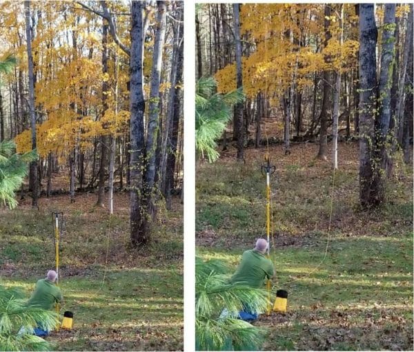
Launching the line
Launching the line

Success, the line is up around 70 feet in the tree

These two pictures fully show the tree to give some scale to how high the end of the antenna is.
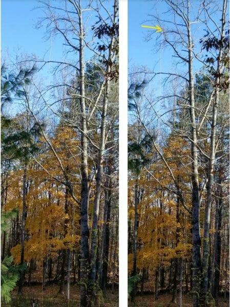
Success 70 feet high

This picture, looking South, shows the antenna feed point around 30 feet high at the house. There are three 10-foot chain link fence top rail sections attached to the corner of the house with a line holding the antenna. From there the ground slopes downhill around twenty feet. The end of the 135-foot wire antenna is hung at seventy feet in the tree. It is running North and South with a little bias to the West.
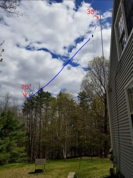
NH QTH EFHW at 70 feet

Did it work?

I was eager to find out if it was going to make a noticeable difference in the contest. It did! On the 20 and 40 meter bands I can get through pileups, often on the first or second try. My first QSO on 80 meters was to Ukraine, around 4500 miles away. In the beginning of May, during the NE QSO Party, for instance, I had replies to my CQ on 80 meters with only 100 watts from Italy and Uruguay.  80 meters was my most productive band in the contest.
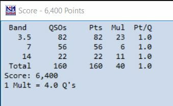
NEQP 2020 Score Box
NEQP 2020 Score Box

Good for Christmas lights, too!

Here is a quick look at the throwline launcher in action. I am sending a line up in a tree to pull up some Christmas lights. Click on the picture to view the video. Each string of lights in the picture on the right represents the arc of the throw-weight and line. The max height in the tree is around 35 feet.
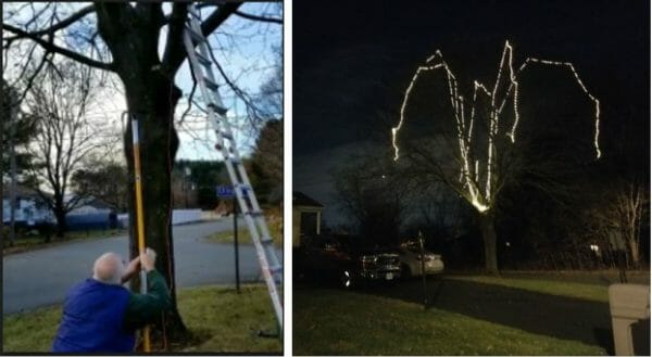
Christmas Lights
Christmas Lights

NARS Winter Field Day 2020

During setup for the Nashua Area Radio Society’s 2020 Winter Field Day the spud launcher, we were using broke after setting up a 40-meter delta loop antenna. We still had to set up the 160 Meter Transmit Antenna. It was a dipole, fed at around 50 feet with each end to be installed around 40 feet high. I made a quick trip home to fetch the throwline launcher. Upon my return it was easy to secure the ends of the dipole up in the trees.

Jon, AC1EV

The Amazing 20m Coil-Shortened “Shower Rod Dipole”.

If you’ve got a few old shower curtain rods hanging around – you can build a low-cost 20m shower rod dipole antenna. Additionally, if you add a tripod, and a matching transformer, and you’ll have a robust field deploy-able antenna. It can also be manually steered for better performance and searching for nulls.

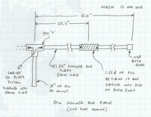
This is the dipole that I used for the ARRL 2019 Field Day and was very happy with its performance. My preference this year was digital modes so I tuned the coils for the magical FT8 14.074 MHz. The original plan diagram is shown in Figure 1 and the coil calculator was used to design the inductors. Anything close to 19-20uH would work for this frequency (14.074 MHz.).

The Plan

Figure 1 – Mechanical plan

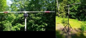
Using a PVC T, about 3 feet of 1.25″OD  PVC pipe, four 24″ aluminum or plated steel shower rod sections, some 14 AWG stranded wire, and a handful of sheet metal screws you really can construct a pretty good dipole for 20m. I tested it mounted on a tripod as shown in Figure 2 and raised to 15-18′. The MFJ-907 transformer, or a torroid assembly similar to the 630m match, will make for an easy match transformer that could be mounted  directly on the “T” section.

Shower Rod Dipole

Figure 2 – Deployed Dipole on Tripod

On one end of the dipole I attached a short piece of kernmantle (nylon) rope which hung to the ground when the antenna was fully extended. This, and slipping the vertical PVC section over a mast tube, allows for turning the dipole for experimenting with nulls and increased Rx performance.

The Big Day

For the ARRL 2019 Field Day, I operated 1BNH using 5W maximum from near the top of Beech Hill in Dublin, NH. (Grid Square FN32xv) Radio was an FT-991 on battery using the built in ATU. Although the road to the summit was washed out this year from spring flooding, I was able to set up on a pretty good high point along Rt 137 just east of the Zig Zag trailhead.

QSO Results !

With only several hours of operating time out of the back of my Jeep I was able to FT8 QSOs with 13 stations in 6 unique call sign zones. Two of the most distant stations were the Halifax ARC (VE1FO) and the Northeastern Missouri ARC (W0CBL).  Noteworthy is that while limited to only 5 Watts for transmitting, I could clearly hear many more stations (as many as 50) then I could actually QSO with.

Station List:
  1. 2019-06-23         09:48     W0RRC 20m        EN34iv

2. 2019-06-23         09:20     K1HTV   20m       FM18ap

3. 2019-06-23         07:59     W3MIE 20m       EN91vp

4. 2019-06-23         07:48     W4XD   20m        FM08jg

5. 2019-06-23         01:13     VE1FO   20m       FN84ep

6. 2019-06-23         01:11     W0CBL 20m       EN30tl

7. 2019-06-23         01:08     W1QV   20m        FN31xi

8. 2019-06-22         19:43     W4HFH 20m      FM18kt

9. 2019-06-22         19:31     K1BX     20m        FN43ec

10. 2019-06-22         19:25     VA3BIC 20m     FN02jv

11. 2019-06-22         18:39     K3NQT 20m      FN00ra

12. 2019-06-22         18:38     VE3XF   20m     EN94xj

13. 2019-06-22         18:33     VA3OBO 20m   FN03bf

The project turned out a great portable antenna for 20m and the performance will definitely surprise you. A subsequent test at home using 100W on FT8, JT9-1, JT9-2, and WSPR, showed no signs of overpowering the antenna. Finally, if any readers have an interest and/or any other questions about this project feel free to contact me directly: [email protected].

73 – Jim, WQ2H / WK2XAH

References:

ARRL, (2015). The ARRL Antenna Book for Radio Communications, 23th Edition. The American Radio Relay League, Inc. Newington, CT

Electronics Notes (1997). Build an HF Ham Radio Dipole Antenna. Retrieved November 12, 2019 from: https://www.electronics-notes.com/articles/antennas-propagation/dipole-antenna/hf-ham-band-dipole-construction-80-40-20-15-10-meters.php

Andersen, S (2019 July 28). When a Dipole Doesn’t Hang in a Tree. NARS Article. Retrieved on November 12, 2019 from: https://www.n1fd.org/2019/07/28/unusual-dipoles/

Build Your Own Low Cost 630m Load/Match

If you have an old wire antenna or even a newer wire that you haven’t been using all that much, consider re-purposing it for a new challenge: Medium Frequency (MF).  Many radio amateurs don’t realize that 630m (475 kHz) is very accessible. For instance, a transverter, QRP transceiver, and a simple load coil and transformer match assembly are all that is usually needed to utilize a new or re-purposed wire antenna.

If you have something close to an inverted-L wire antenna, say with a 35 feet vertical section and a 50-100 foot horizontal section, you are very close to having a reasonably efficient short top-hatted Marconi antenna for MF. It will never be resonant but will be a good Rx/Tx performer. Additionally, they will work very well for North American NDB, Non-Directional Beacon, reception. These antennas will work perfectly with any of the commercially available transverters such as the Monitor Sensors, TAPR QRP transmitters, or the popular K5DNL PA for 630m. Using any of the on-line calculators to figure out exactly what inductance load you need based on your specific wire configuration has never been easier. For example, VK1SV maintains an excellent short Marconi calculator here. It gives you all the parameters for a wide range of frequencies and wire types.

The Project

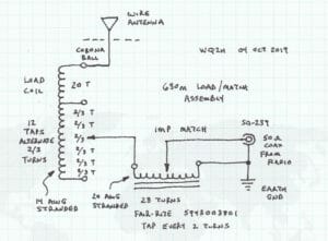
This project was to re-purpose an existing older wire inverted-L that I wasn’t using. The wire was composed of a 35’ vertical section and a 100’ horizontal section. First of all, using the online calculator gave me a rough estimate of around 100 uH needed to utilize my existing wire. Then, using an inductance coil calculator, I arrived at the least expensive method to build the inductor, using two 8” PVC couplings (glued together) and about 100’ of 14 AWG stranded wire. A liberal span of internal taps was included for adjustability and tuning.  I also added an SO-239 connector. As a result, the coax attachment will be much easier. Also, placing a small corona ball on the antenna side will provide additional protection from the kiloVolts of antenna voltage.

The matching transformer was tie-wrapped to the inside of the inductor. It was built simply by taping two Fair-Rite type 43, 61mm OD, cores together and using 28 turns tapping every two turns. Care must be taken to attach the toroid assembly outside of the inductance coil zone. One side of the transformer is connected to ground and the other contained an alligator clip for easily attaching to the load coil tap. The schematic diagram and mechanical configuration are shown in Figures 1 and 2.

Figure 1 (adapting Dennison, 2013 p 37) (1)

Figure 2 (1)

A Low-Cost Enclosure

The entire assembly is small enough (~ 8” dia. X 12” high) to fit in a two and a half (2.5) gallon pail. You can manage the cables through a separate snap-on lid. The pail yields a waterproof assembly that can be left outside of the shack and at the base of the vertical wire section. This keeps the “hot side” of the coil and higher voltages away from your shack and house. Most importantly,  a separate earth ground connection is required. Using a single vertical ground rod, position it close to the SO-239 connector. As a result, most stations will see improved performance. See Figure 3. While radials would also certainly improve performance I have yet to experiment with adding them. A PolyPhaser or spark gap can also be added for static/lightning protection.

Make sure to isolate the antenna (hot) side on the coil and antenna wire. Additionally, using insulators at the antenna wire extremities and bend point is always necessary. As a result, this will provide isolation from the several kiloVolts of voltage that will be present on the wire during 630m transmit.

Figure 3 (1)

Testing and Performance

CAUTION – High Voltage (~2kV) will be present at the antenna feed point during testing. Moving the alligator clips to achieve the best match is an iterative process and may take several attempts. Do not attempt to work on or adjust the Load/Match unless the coax feed line is disconnected and the radio is turned off.

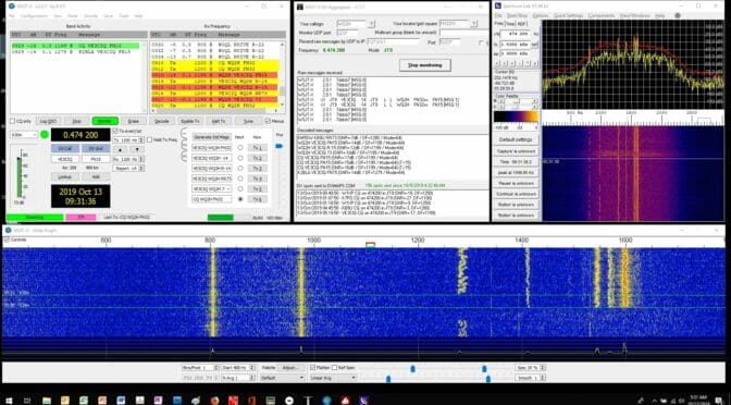
The first radio test went very well. (beginner’s luck I suppose) The lowest SWR I could achieve was 1.4:1. However, a higher resolution on the tap spacing would probably have yielded a better ratio. But this was plenty good enough for a first test for the time being. I used a Monitor Sensors TVTR1 transverter with a conventional HF transceiver. As a result, I was able to make about a dozen 630m JT9-1 QSO’s in the first week using the repurposed wire and homebrew load match assembly. Likewise using the WSJT DX Aggregator, I was also able to report activity by over 60 stations across the country. See Figures 4 and 5.

From the calculator, given 50W into the load coil would yield about 500mW EIRP. While this is clearly inefficient by any measure, it is plenty of power at 630m to reach across the continental U.S., and potentially beyond.

Figure 4 – 630m JT9-1 QSO (1)

Figure 5 – First 630m JT9-1 Rx reports from FN32xv (2)

Results

As of 24 Oct 2019 the Rx record is W7IUV 3715 km @ -27 dB S/N, and JT9-1 QSO record is KB8U 1027 km @-25 dB S/N. Given the low cost, the amount of time to build, and the immediate on-air results, this approach for an MF load coil/match assembly is a worthwhile project for anyone wishing to explore MF.

Finally, the bulk of the cost for MF capability will still be the transceiver. However, if you’re a project builder with good patience and soldering skills, the TAPR Ultimate 3S kit for $33 is a good introduction. Also, the TAPR transceivers make available an LPF for 2200m – but that’s an entirely different can of worms. (The short Marconi calculator will show you that!) If any readers have an interest and/or any other questions about this project feel free to contact me directly: [email protected].

73 – Jim, WQ2H / WK2XAH


References

Dennison, M (2013). LF Today – A Guide to Success on the Bands Below 1MHz. Radio Society of Great Britain, London

Giles-Clark, J (2014),  630m (472-479kHz) Amateur Experimentation VK/ZL, Presentation. Retrieved October 24, 2019 from: http://www.spirat.com.au/vk5fq/media/630m_in_VK-ZL.pdf

Kelly, P (2019). Adding 630 and 2200 Meters to the MFJ-259B. N1BUG Adventures in Radio. Retrieved October 24, 2019 from: http://blog.n1bug.com/2016/12/22/adding-630-and-2200-meters-to-the-mfj-259b/

Severns, R (2017). Capacitive Top Loading. Antennas By N6LF. Retrieved October 24, 2019 from: https://rudys.typepad.com/files/chapter-3–1.pdf

Spirat, S (2018). 630m loaded Inverted L Antenna. VK5FQ Antennas. Retrieved October 24, 2019 from: http://www.spirat.com.au/vk5fq/630mAnt.htmlhttp://www.spirat.com.au/vk5fq/630mAnt.html

Carey, K (2007). Listening to Longwave – The World Below 500 KiloHertz. Universal Radio Research. Worthington, OH

Ouwehand, M (2017) 472 kHz Projects – Antennas. Retrieved October 24, 2019 from: http://www.pg1n.nl/articles.php?lng=en&pg=1270

(1) Image courtesy of WQ2H – Jim Poulette

(2) Image courtesy of PSK reporter and OpenMapTiles.org

Radio Amateurs Developing Skills Worldwide