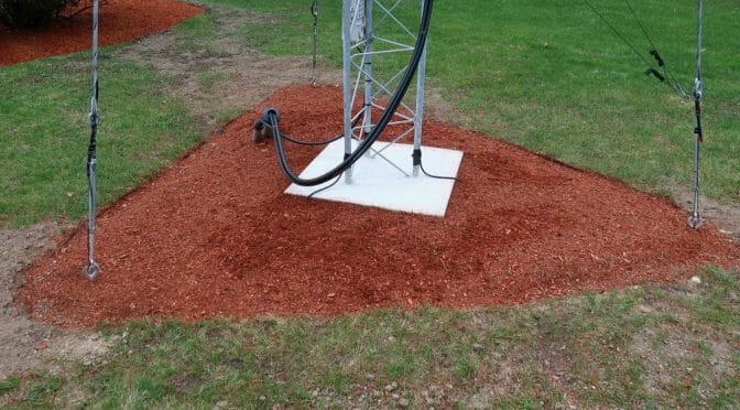
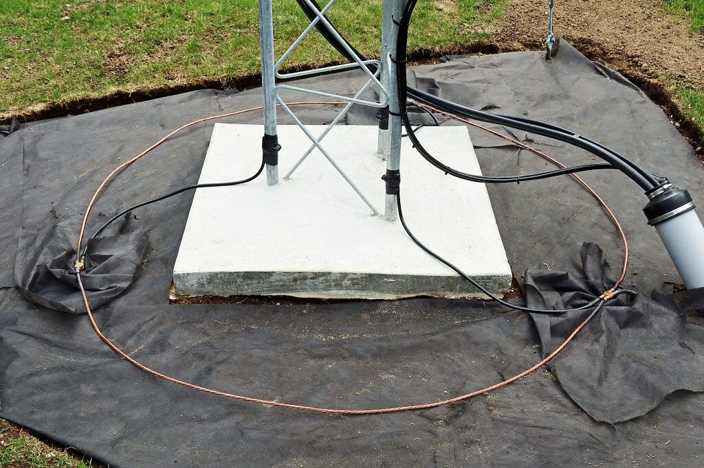
The most recent project was to build complete the ground system for our new EME tower. Tower grounding is often done incorrectly. The proper way to ground a tower is shown above. Each leg of the tower is connected to an 8′ ground rod via a heavy-gauge ground cable. The cable is attached to the tower leg using stainless steel clamps meant for this purpose. The three ground rods associated with the tower legs are then bonded together using a heavy copper ground cable ring.
Ever wonder how to go about grounding and bonding a tower? It’s not difficult to do this correctly. Most of the materials that are required are available at local hardware stores or online via DX Engineering. The required materials include ground rods, heavy stranded grounding cables, ground clamps, and/or a thermal welding system to connect the cables.
Tower Grounding System
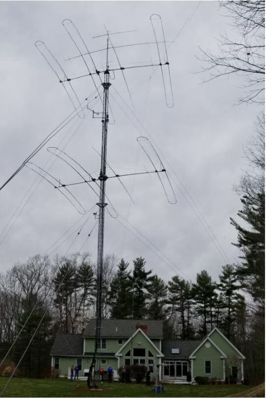
We recently put up a new tower at our station to support a 2m EME station that we are building. This provided a chance to show how to properly ground a tower. The photo above shows the completed ground system for our new EME tower. The link above explains the details.
I have been a ham for a little over two years now. In that short time, I have had a chance to try out many of the different things one can do. One exciting thing to do is to participate in a contest. Many of us have seen pictures and read articles of serious contesting stations and may even drool a bit for all the high-end hardware and giant antenna farms. I plead guilty myself.
As a new ham, my station has, for the most part, been a basic one. I have an excellent radio in the IC-7300, which priced to be available as a high-end entry-level radio. At this stage in my ham radio adventure, I am not sure I can appreciate the advanced features found in the higher end radios, yet. In the beginning, using my IC-7300 and a Buckmaster 7 Band Off-Center Fed Dipole and running 100 watts many of the stations I was able to contact were contesting stations. Their great antennas and sensitive receivers could pull out my signal with ease. Time passed and my station is improved, now with 500 watts and a hex beam or wire antenna up over 45 feet high and I can compete for attention in a pile-up in a contest.
Unless things are quiet or slow due to the hour, I haven’t had great results running on a frequency in a contest, but search and pounce, where the operator finds a station and replies to their CQ, works well and I am often heard first try. Just that bit is loads of fun and satisfying. I enjoy seeing how my radio performs and contacting people in different places, so entering a contest is fun, even though I know I am not going to be competitive. It is obvious, but I will say it anyway, there are lots of people on the air during a contest. That means it is a great time to make QSOs, even though you are not going to rag chew or be a contender.
Operating From AB1OC-AB1QB
I had a chance to operate from a contest grade station last year for around 4 hours during a CQ WW SSB contest. Thanks to AB1OC Fred and AB1QB Anita for their generosity.
Stacked SteppIRs
Their station had stacked Steppir antennas and 1500 watts of power so when I talked, people heard me!
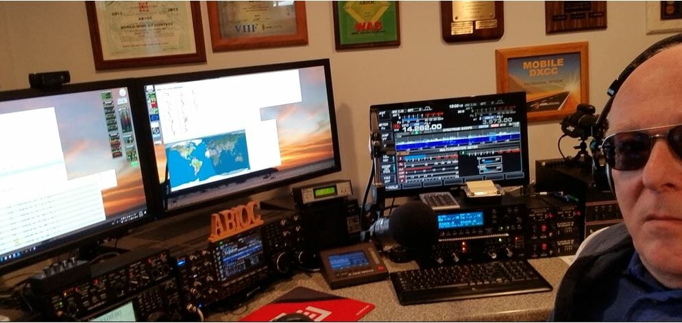
Operating from AB1OC Station
Operating From My QTH
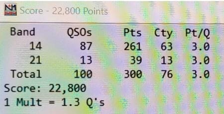
In those 4 hours, I made 99 QSOs on SSB and got 78 different countries! 6 new ones for me, too! It was exciting, so when the North America QSO Party contest came around, I decided I would see how I could do on my own station in the same amount of time. It turned out that I was able to make 100 QSOs and 76 multipliers in 4 hours for that contest, which I thought was respectable given the difference between our stations.
North America QSO Party
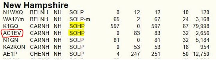
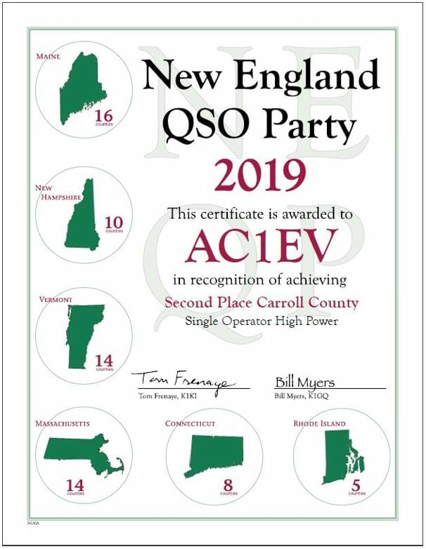
As I described above, I only dabbled a bit with contests, yet I had lots of fun. I strongly suggest that you try it out for yourself. I also strongly suggest that you participate fully and submit an official log to the contest when it is over. The first reason is that it makes your QSOs count for the people you contact and the other is that you might be surprised and get a certificate! For new hams, you might be able to submit as a rookie and then you are competing against other rookies and not the big guns. Some contests have other “side” contests in their scoring, so you might pick up something there. Last year I spent around 9 hours in the New England QSO Party contest from my second house, which is in Carroll County, New Hampshire. There are only 147 licensed hams in Carroll county and only 4 entered the contest.
2019 NEQP Competition
NEQP NH Counties
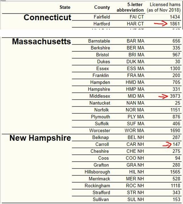
You can see in the tables below the populations of licensed hams by county. Middlesex County, Massachusetts has the largest amount of licensed hams in New England! I admit I did not know that, but after thinking about it, it is not surprising. The next largest county is Hartford, CT and it is only half of Middlesex. If you are trying to win a ham radio contest from one of these counties, you will need a serious station and be willing to spend lots of time in the chair.
CT MA NH Counties
Remote Contest Logging
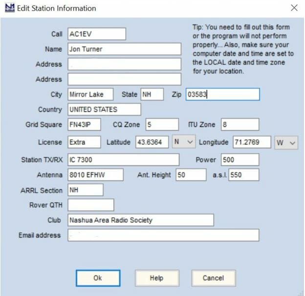
When you operate in a contest you enter your station information in the logger and that is how your location is determined. My home QTH for my license is in Tewksbury, MA but the contest logger needs to have the location of the station you are operating for the contest. When I participated in the NE QSO Party in May 2019 I setup N1MM+ logger like this:
N1MM Station Info NH QTH
I was not trying to win the contest. I thought it would be a good opportunity to make lots of contacts and when you encounter someone you contacted in the contest in a future QSO, you have a good start on beginning a rag chew.
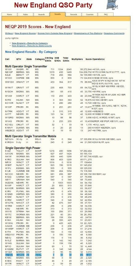
Overall NEQP 2019 Results
Here are the results of the 2019 NEQP. It may be worth looking at previous years’ results for contests you want to compete in to see how the top finishers scored. If you can choose the location you will operate from, this can help as well.
NEQP 2019 Scores
Here is the surprise I received from the 2019 NE QSOP, which prompted this article. The 2020 NEQP is May 2 – 3, give it a try.
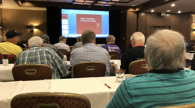
The 2020 Dayton Hamvention has been canceled, but you still have the opportunity to attend Contest University from the comfort of your QTH! The organizers of Contest University will be holding a free Virtual Contest University via Zoom on May 14th.
Contest University is a full day of educational presentations. The world’s most skilled contesters share their knowledge. You will learn not just how to operate in a contest but skills that are useful for all ham radio operators:
How to improve your station
All about propagation and when to operate to get the most and most distant contacts
Information on setting up your digital station and operating digital modes,
What are the best performing transceivers based on testing by Rob Sherwood, NC0B
And much more!
Fred, AB1OC, and I have been attending Contest University for many years and we learn something new every time. Contest University is highly recommended for our Student/Teacher Contesters as well as all of our members.
You can register online for the Virtual Contest University at the above link to get the Zoom link. Contest University starts at 8:30 am on May 14th.
Radio Amateurs Developing Skills Worldwide
We use cookies to ensure that we give you the best experience on our website. If you continue to use this site we will assume that you are happy with it.