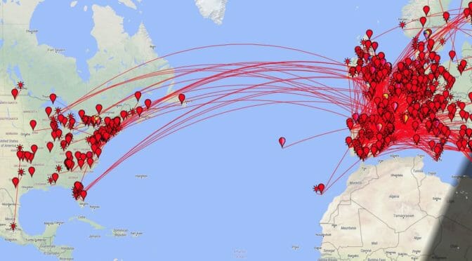
I’ve had a chance to operate on the 6m Band this past week. We are approaching the prime time for the summer Es (E-Skip) season here in the Northeastern United States. I was fortunate to catch a typical limited DX opening on the 6m band between our location here in New England and Europe…
The spring 6m Es season is well underway here in New England. We are beginning to see some DX opening to Europe daily. As a result, I thought that it might be a good time to share some information about 6m DX openings using some examples captured during a recent operating session here at AB1OC-AB1QB. The link above contains the details.
The article illustrates what a typical 6m opening to Europe from here in New England is like. It also includes some information about how to monitor the 6m band to spot short-lived DX openings when they occur.
FT8 mode, JTDX software, and PSKReporter are described in the article at the link above. These are useful tools for monitoring propagation and working contacts on the 6m Band.
I hope that you’ll give the 6m Magic Band a try this Es season!
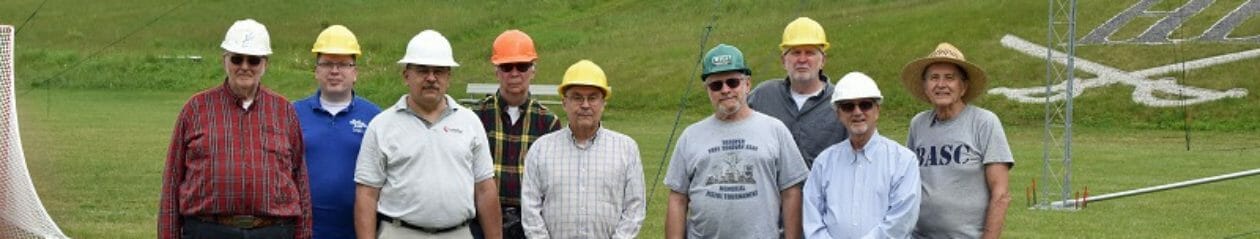
When the Nashua Area Radio Society’s Student/Teacher Contest Series was first set up, Fred and Anita (AB1OC/AB1QB) offered up their station to my son Keith (KC1IMK) and other students that do not have a station at home. Fred and Anita have an amazing station at their QTH and you can find more information on it here.
Then COVID arrived and sharing mikes, headphones, and keyboards at other people’s houses are no longer acceptable. We cannot risk getting each other sick. Another way is necessary. Remote Operation is here!
Fred (AB1OC) and Jamey (AC1DC) worked out the kinks for setting up Remote Operation first. Then Fred invited Keith and me to try it out. After a couple of hours online with Fred to set up, we were on our own. Contest Calendar showed the Helvetia Contest that night so we pointed the beams toward Switzerland and called CQ. Several stations pounced on Keith at once. He worked hard with the mouse, bouncing from the radio PTT button to logging in N1MM. Once the pile-up was cleared, he pulled off his headset and said “I really wish I had a footswitch like Field Day“.
Remote PTT Switch for SmartSDR
Driven to maintain my “Super-Dad” status, I went to work. I found a few references at the FlexRadio site:
Looked pretty straight forward to build a Remote PTT Switch. Configure a SmartSDR CAT interface to monitor hardware flow control pins in a standard serial port. The hard part today is to find a serial port. They have all been replaced by USB.
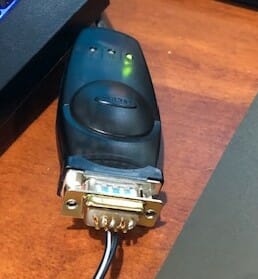
I dug out a 15-year-old Belkin adapter from the back of my shack and installed it. A new Com3 port showed up in Windows 10 device manager.
USB to Serial Adapter
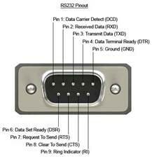
SmartSDR CAT will detect if RTS is shorted to CTS in a Com port.
This is a very standardized interface and it was easy to find the pin definition.
Pin 7 is RTS
Pin 8 is CTS.
Easy to spot as they are the center two pins of the row of four.
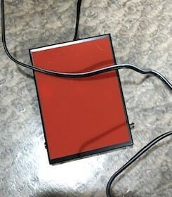
I also had the mating 9 pin D connector in my bin of parts. One could probably solder to the pins of the adapter, but I would recommend a connector. I cut off the 1/4″ plug from a footswitch I bought from Amazon. The two leads were soldered to pins 7 & 8.
To test it, I downloaded ComTestSerial from Microridge https://www.microridge.com The test software confirmed the hardware worked. Each time I pressed and released the footswitch the CTS light in the top right corner changed between Red and Green.
Configuring FlexRadio SmartSDR
Now to configure the software. Open SmartSDR CAT and add a port. Give it a name. Set Port Protocol to PTT, set Port type to Serial, set Serial Port to Existing, and set CAT COM to your new Com port. Mine was Com3. Set VFO slice A. Select RTS. Hit save.
CAT settings
I found some open spectrum on 20m, crossed fingers, and pressed the switch.
Voila! It transmitted!
With prolonged use, I found my old adapter was not up to the job. The drivers were not meant for Windows 10. It missed about 1 out of 10 switch presses. I have since upgraded and the new Remote PTT Switch works great.
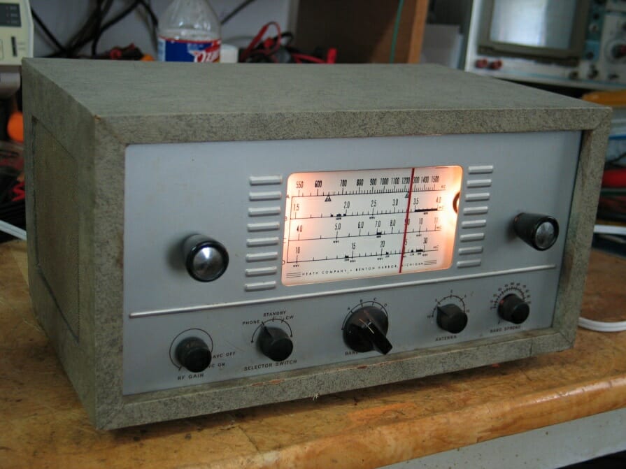
I obtained my FCC Novice license in 1957 at age 13. At that time, I didn’t yet have a station, so I set out to remedy that situation. I had been using a Heathkit AR-3 receiver (4 tube superhet, $29.95 in kit form, cabinet $4.95 extra) I built prior to obtaining my license; while OK for SWLing, it wasn’t well suited to amateur radio work. My first priority was building a homebrew transmitter while looking for a more suitable but affordable receiver. While I was building the transmitter, my father borrowed a WWII German military receiver from a colleague at work for me to use temporarily. I didn’t know it at the time, but this receiver was a quite sophisticated design. I used this receiver for several months (including for my first ever QSO), but didn’t pay much attention to the details as most of the labeling was in a language I didn’t understand, and I had no manual, other documentation, or knowledgeable guidance.
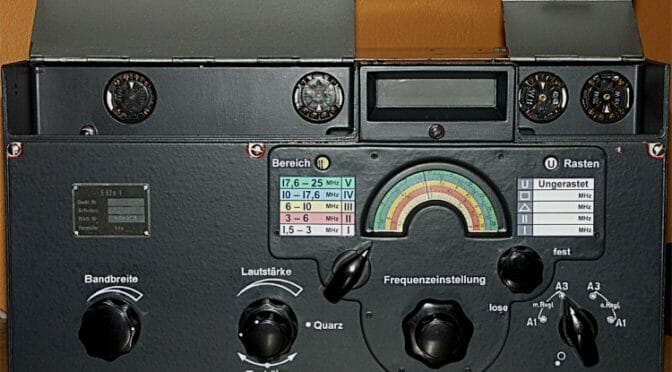
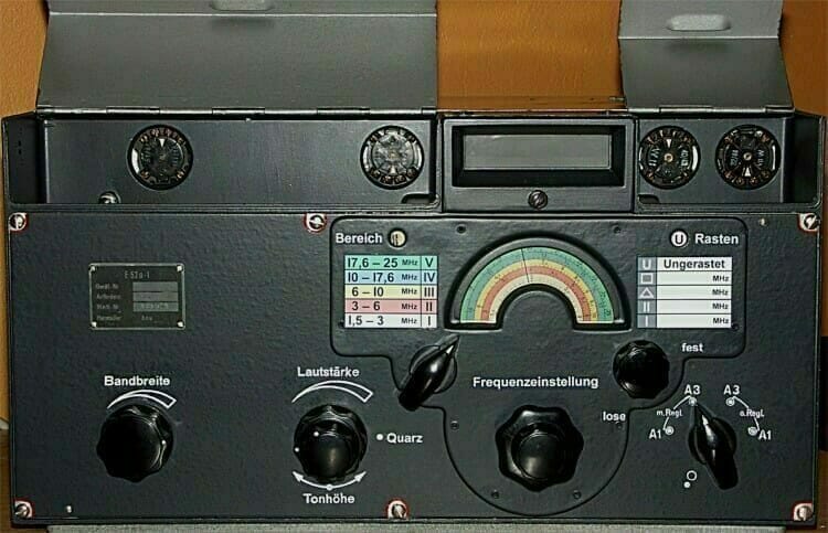
I recently decided to see if I could more precisely identify this receiver based on my recall of a few unique features of the design. One very clear recollection is that the frequency display was projected onto a ground glass screen on the front panel. This turned out to be the definitive clue in identifying this receiver. Another recollection is the strange-looking (to me, at least) vacuum tubes, the bases of some of which could be seen by opening two flip-up covers on the front panel. Using these clues, it was easy, with some internet research, to zero in on the make and model of the receiver. It was a Tekefunken E52 series manufactured in several variations mainly for the German Luftwaffe between about 1942 and 1945. At the time, I had no understanding of the advanced nature of this design; it was way ahead of its time, and only about 2500 were built. Below are some photos, snippets, and links from the websites I visited. While likely of limited interest to newer hams, in these days of pandemics, lockdowns, and self-isolating, perhaps an interesting diversion. Much more information on the web for those so inclined.
“This is one of the most studied, written about, and discussed receivers in the world”
History:
Empfänger 52 was specified by the Reichsluftfahrtministerium (RLM) in 1939 as one in a series of five similar receivers covering the entire frequency spectrum from LF to UHF, intended for use in the Luftwaffe ground stations, but also for other services and authorities. A request for quotation went out to a few German electronics manufacturers and Telefunken developed and built a prototype of the short wave receiver Köln in the beginning of 1941. Telefunken was chosen to manufacture the series of receivers according to their specification ”Luftboden-Empf.-Programm 2 – 7500 m für die Bodenausrüstung der Deutschen Luftwaffe”, Telefunken Berlin-Zehlendorf 5.5.1941.
Out of four specified receivers E51 Leipzig (LF), E52 Köln (HF), E53 Ulm (VHF), and E54 Kulm (UHF) only Köln was built in large series. In total around 2500 receivers were built from July 1942 to March 1945. The E52 was made in 10 models, of which the E52a-1 (simplified with automatic tuning) and E52b-2 (simplified with manual tuning and unified scale) were the most common. Of all the E52s built there are probably 300 – 500 left, of these perhaps 50 in their original state.
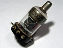
The receiver is modularised, the modules are mounted in a molded aluminum chassis and all connections between the modules are through connectors in a backplane! Both the construction and the performance were far ahead of its time. Only one type of valve, the RV12P2000, was used in the receiver except for the power rectifiers. The intention was that all modules and valves should be interchangeable in the field without the need for realignment. The first test series of around 20 receivers were made in Sachsenwerk in Radeberg from July 1942 of the simplified type E52a-1 and possibly also the type E52b-1. The manufacture was not up to speed until the beginning of 1943. The assembly and alignment were made in Sachsenwerk Niedersedlitz while the modules were made in several different electronics industries.
Receiver data:
The receiver is an advanced single superheterodyne with two RF stages, a mixer/local oscillator, three IF stages, a detector/BFO/AF amplifier, and an output stage for headphones. In total there are 6 tuned circuits in the RF/mixer/oscillator part and the receiver has very high sensitivity and selectivity. The IF stages have a 6-circuit filter plus 4 tunable circuits in a variable crystal filter, the bandwidth is variable from +/- 5 kHz down to +/- 200 Hz @-3dB with very steep slopes, damping 100 times at +/- 10 kHz in wide. The tuning has a coarse scale and a fine-scale projected from a micro photo disc with very high resolution and accuracy. The oscillator has very accurate temperature compensation and thus high stability. Frequency coverage is 1.5 to 25 Mhz in five bands, the sensitivity for AM 3 – 5 uV, CW wide 1.0 uV, and CW narrow 0.3 uV for 5 V output. Mirror frequency damping is at least 50000 and the IF damping is better than 100000 at 1.5 MHz. The stability is better than 30x 10E-6/degree C, which is 30 Hz/MHz/degree C for a freerunning oscillator! Even today this is competitive against many modern receivers comparing sensitivity, selectivity, and stability.
We use cookies to ensure that we give you the best experience on our website. If you continue to use this site we will assume that you are happy with it.