Category Archives: Featured

This category is for featured articles that we want to include in the sidebars and other areas on our website.

Yagi Antenna Construct Part #2: Current, Voltage Profiles, and Dipole Pattern

In Part 1 of this article series, I presented the “Lego” 2 m 3-element Yagi antenna design that the N1FD ham license teaching team has used over the past year for class demonstrations.  The design allows easy assembly of the basic dipole antenna as well as a 3 element Yagi. The configuration of individual elements and spacing between elements can be quickly changed to demonstrate basic physics and behavior of these popular antennas.

The first article described antenna construction details and showed how to demonstrate the criterion for resonance as well as the polarization property of the radio wave.  In Part 2 of the series, I will continue a focus on the dipole, specifically the spatial current – voltage profiles on the driven element and the radiation pattern of the antenna.  We will use this information in Part 3 of the series next month to demonstrate how a 3-element Yagi works and why it is so popular.

THE CURRENT & VOLTAGE PROFILES ON A HALF WAVELENGTH DIPOLE   

Current Profile on a Half Wave Dipole Antenna
Figures 1a and b – Current Profile on a Half Wave Dipole Antenna

Figure 1a reminds us of the basic dipole geometry; and Fig. 1b shows the current and voltage profiles along the driven element.  (From http://www.radio-electronics.com/info/antennas/dipole/half-wave-dipole.php)

Note from Fig. 1b that the current profile of a dipole has a maximum current level at the center feedpoint and decreases to zero current at the end of each element arm.  Contrasting, the voltage profile has a zero value at the feed point and increases to a maximum level at the ends of the element arms.

1/4 Wave Vertical. Note the 7 spaced lamps.
Figure 2 – 1/4 Wave Vertical. Note the 7 spaced lamps.

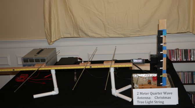
The 1/4 wave vertical antenna seen in Figure 2 can be used to visualize the current profile along the arms of a 1/2 wave dipole.  The 1/4 wave antenna is made from a short length of a Christmas tree (incandescent) light string.  The string length can be estimated from the standard equation:  Length (ft) = 234/Frequency in MHz. Generally, several inches needs to be trimmed off because the lamps add “electrical length”. The shown antenna has the same resonance frequency as the Lego Style dipole we will use later (i.e., 146.550 MHz). The top end of the antenna is marked by the blue tape immediately above the 7th lamp.

Transmitting mode. Note pattern of lit and unlit lamps.
Figure 3 – Transmitting mode. Note pattern of lit and unlit lamps.

The energized antenna with 15 watts RF signal is seen in Figure 3.  Compare the pattern of lit and unlit lamps with the current profile sketch shown in Fig. 2b.  The three lamps, counting from the picture bottom are brightly lit from an RF current.  Lamps 4 and 5 show progressed less light indicating a lower RF current.  Lamp number 6 is barely lit and number 7 is dark indicating together very little to no RF current at the element top end.  The light pattern is a clear mimic of the diagram in Figure 1b.

Demonstration of the Voltage and RF Radiation Profile on a Half Wave Dipole Antenna

The voltage profile on a center fed 1/2  wavelength dipole is seen in Figure 1b. As mentioned above, the voltage is zero at the dipole center and increases in monotonic fashion to a maximum value at the antenna ends.

Illustration of Dipole RF Radiation Pattern
Figure 4 – Illustration of Dipole RF Radiation Pattern

The familiar RF radiation pattern of a dipole is shown in Figure 4 (taken from the cited source for Figure 1).

We are all well-schooled on the pattern, so I will just list the three key facts.  First, the RF radiation is broadside to the antenna axis. Second, the RF field intensity is equal on the left and right sides of the dipole axis (i.e., there is no discerned “front to back” sidedness. Third, there is (theoretically) no RF radiation off the ends of the dipole wire.

The dipole voltage profile and the RF radiation pattern can be demonstrated using the basic dipole element of our “Lego Style” antenna and two simple tools. The voltage profile, or more correctly, the electric field strength around the dipole is sensed by a small fluorescent light tube.  The actual RF radiation from the energized dipole is sensed by the flashlight lamp-bridged receiver antenna introduced last month in Part 1 of this series.

  1. Direct RF Radiation Visual Detection

The video below (double-click in the picture box) demonstrates the use of the lamp-bridged receiver antenna to detect radiated RF power.

The video shows the flashlight bulb bridging the handheld receiver antenna lights up when it detects an RF signal that matches its resonance point at 146.550 MHz  The light bulb is dark with no transmitted RF power from the Lego dipole. Keying the radio energizes the Lego dipole and the receiver lights up about equally on the right and left sides of the Lego antenna.  This reflects the figure 8 pattern of RF power illustrated in Figure 4.

  1. Voltage Profile witnessed by the Electric Field Strength.

The next video (double-click in the picture box) employs the fluorescent light bulb to map the voltage profile along a dipole arm by sensing its electric field strength.  An RF electric field causes a series of chemical reactions within the light bulb that produces a bright fluorescent light.

The light bulb is dark when the Lego dipole is not transmitting an RF signal. Keying the radio generates an RF signal and the associated electric field around the dipole element causes the bulb to light up. Note, the bulb is very bright adjacent with the side end of the dipole arm and extinguishes as it is moved to the dipole centered feedpoint. Also, the light is dimmed at the antenna tip in-line with the dipole axis.

The voltage profile map seen in the fluorescent light bulb video augments the RF signal map seen in the lamp-bridged receiver antenna video.  Also, it extends our demonstration to the expected observation that there is (theoretically) no RF radiation off the end tips of dipole elements.

CONCLUSION 

In this second installment of our Lego-Style Antenna series, we have shown how this construct together with two simple tools can be used in the classroom to demonstrate basic properties of the ubiquitous dipole antenna; Namely, criterion of resonance, generation of RF radiated waves, the polarization of the RF field (horizontal or vertical) and the general propagation geometry of these waves relative to the antenna orientation.

In Part 3 and last installment of this series we will continue to use the Lego-Style Antenna in its’ Yagi configuration together with the two accessory tools to show how properly designed and placed reflector and director elements on the Yagi antenna can shape and control the dipole rf signal to increase gain via spatial directivity  and improve signal selectivity by the “front-to-back” ratio that it creates.

73 & Hope to hear you on the air,

Dave N1RF

Moxons in the Attic (Part 1)

A few months ago, I wrote an article on building a stealth antenna farm. Since I live in the land of CC&Rs, antennas must be “dual use” such as a vertical hidden inside a PVC flagpole, or low dipoles and inverted Vees hidden in trees. I spent many years as an avid contester and DX-chaser to appreciate the logic of stacked beams on towers to enhance the thrill of the hunt. Thanks to Layne, AE1N, I checked out the website of Jeff, AC0C (www.acoc.com) for some ideas of how to build a multi-band station in one’s attic without the condo association vigilantes running him out of town. Jeff spent countless hours crawling around his attic to construct multi-element antennas for 160 through 6 meters. Spurred on by Jeff’s success, I decided to explore the attic of my garage to see what I could do. As I described in the MAY Nashua ARC bulletin, I settled on building Moxon antennas for 15 and 17 meters.

An old adage about antenna building states that an antenna must be built-in lousy weather in order to work right. Thirty years in New Hampshire lent credence to this axiom as I spent many a cold, windy day on a tower doing antenna work. In Florida, a similar law applies: build an antenna in the summer months while sweating profusely rather than during the comfortable winter weather. Again this makes sense: DX and contesting fill up the winter months to have time to mess with antennas. It is also important to remember that, during such endeavors, you will become enamored with you antenna as you take breaks to warm your body (in NH) or drink a gallon of water (in FL), all the while cursing this law of antenna building.

But I’m getting ahead of myself. My garage attic is roughly 20 x 20 feet with an apex of about five feet that runs north-south. I had selected the Moxon design because a conventional 2-element beam would not fit in the space available. I elected to build a Moxon for 15 and 17 meters that would fit in the space available without having to encounter obstacles like the ventilation duct work. I was also fortunate in that my home is one of the older models that do not have foil-backed insulation inside the roof that creates a radiation-proof box. The joists junctions are reinforced with metal plates as part of hurricane building codes. My plan was to attach the wires to the roof trusses and stay away from these plates as much as possible to avoid interaction.

The 17-meter Moxon is a little over seven feet between elements while the 15-meter Moxon is about six feet between elements. I used a piece of half-inch PVC pipe as a template to mark the joists for the 17-meter antenna. The antenna is about 2.5 feet above the attic floor for a total height of eleven feet above the ground. I had modeled it at 13 feet so I figured it would be close enough. The 15-meter Moxon is about 15 inches above the 17-meter one. When viewed from the top, the antennas look like concentric rectangular loops.

Over the course of several weeks, I grunted, groaned and sweated my way back and forth measuring and installing the wires. I worked during the morning hours before I was soaked before 10:00 AM. I found myself wishing I could have my five-year-old grandson help me. He can stand upright and is plenty flexible to maneuver around the joists. While I did not have to worry about the obvious safety issue of working on a tower, I did at times feel I was a candidate for the NFL concussion protocol from bumping my head. I tried using my cycling helmet but it interfered with my headlamp. Another similarity to tower work is that I had to make N trips back and forth in the attic for stuff I forgot. This is, however, much more bearable that climbing up and down a tower to get what I forgot.

Figure 1 shows a view toward the south end of the attic. The two pieces of PVC form the element separators for the 15-meter Moxon (top wire) and the 17-meter Moxon (bottom wire).

Figure 1 – Moxon Element Separators, 15m (top) & 17m (bottom)

Figure 2 shows the reflector elements for each antenna as secured to the joists, looking north through the attic. The white standoff fasteners are coax cable tie-downs that I found at the hardware store. Standard house wiring fasteners would have worked but they leave little room for pulling wires if I needed to make adjustments. (My first attempt was to use duct tape to hold the elements up. However, the heat soon made them droop.)

Figure 2 – Moxon Reflector Elements, 15 m (top) & 17m (bottom)

Figure 3 shows one corner of the director of each antenna looking east. The duct work to the left is part of the ventilation system while the open duct vents directly from the garage below. The yellow fence standoff on the upper antenna is the bend point for one end of the 15-meter director. Not visible to the left is a similar bend point for the 17-meter director.

Stealth Antenna - Looking East-from the Reflectors
Figure 3 – Looking East-from the Reflectors

Figure 4 shows the temporary feed points for each antenna.

Stealth Antenna – Feedpoint for 15m (top) & 17m (bottom)
Figure 4 – Feedpoint for 15m (top) & 17m (bottom)

The figures above show the project to date. I installed the 17-meter antenna first and measured its SWR performance with my analyzer. I found that it resonated beautifully at 16.7 MHz with a 1.1:1 SWR while bulging to 3.9:1 at 18.1 MHz. I shortened each element by a foot and ran measurements again, this time the resonant point moved up to 17.3 MHz (1.3:1 SWR) and the SWR at 18.1 MHz dropped to 2.7:1. I folded the elements back another four inches on each end and measured the response. I observed the SWR bottoming out at 1.5:1 at 18.1 MHz where I wanted to be. As a point of interest, I modeled a Moxon designed for 16.7 MHz and noticed the elements were about two feet longer than a Moxon designed for 18.1 MHz, close to the twenty inches I had to shorten the elements. Apparently, there is some interaction with the wiring that runs along the attic floor near the edges.

Armed with the satisfaction I was on the right track, I installed the 15-meter Moxon above the 17-meter antenna. I hooked up the analyzer and fired it up only to find to that its “resonant” point was a dismal 3.0:1 SWR at 22.9 MHz, rising to 3.9:1 at 21.1 MHz. This meant my antenna was too short. I went back to EZNEC, opened the standard dipole model and plugged in 22.9 MHz and found that its length was very close to the overall driven element for a Moxon designed for 21.1 MHz. I lengthened each element by five inches as a starting point to see what would happen. The result was no change in SWR at 22.9 MHz while dropping slightly to 3.6:1at 21.1 MHz. Hmm, looks like I need to get a little smarter about this.

Stay tuned for Part 2 to find out. (Don’t you hate that?)

Ed, K2TE

Boxboro Youth Outreach Summary

I had the pleasure this past Saturday to attend the Boxboro Hamfest with many members of Nashua ARC. Amidst all the talks, activities, vendor booths, and flea markets, one component I was interested in was attending the Youth Forum. As some of you know, Jamey (KC1ENX) and I (AB1ZO), are spearheading Nashua ARC’s involvement with recruiting and extending our membership to include young people; specifically targeting young folks 18 and under. We already have one such star in the club, Jamey’s daughter Abby (KC1FFX), who serves as Youth Advocate on the board. This forum was important for Jamey and me to attend in order to extract lessons learned from other clubs who have successfully built an infrastructure based around attracting and retaining young people. Also in attendance (from what I could see) was Skip (K1NKR) whom many of you know has been active with the Girl Scouts and Thinking Day on the Air. The remainder of this article, therefore, will be to summarize lessons I learned and hopefully engender a discussion among interested parties of what we can do in the coming months. As a relevant aside, I truly believe this all can only work, if we have large buy-in from you as the members, so your input is certainly requested and valued. Lastly, get a good cup of hot-joe, you’re in for a long read…at least I’m honest 🙂

When the Forum began, the audience was faced with a large panel of kids all under 18. Easily 10-12 kids, with a majority of them possessing their General license. Many (if not all) were active members of the Clay Center Amateur Radio Club (and even held positions in the club) which has a whopping 260 members. They boast interesting facts:

  • 12 former astronauts have visited the club
  • The meeting area for the club also has an astro observatory so kids can star-gaze as well
  • Roughly 93 out of 260 members are under 18. (One interesting side note is that if a young person was under 16, then their parents also joined as well due to club guidelines.)
  • Many of these kids are also students at a local high school in Brookline, MA: namely Dexter Southfield High School.

One of the club’s mentors is Bob (K5TEC), who has been involved with amateur radio and working with kids for over 20 years; his day job (when he is not a weekend warrior on the radio) is a teacher at the aforementioned high school.

Essentially,  after a brief introduction by the students regarding their age, license level, and background, the Q&A ensued. The audience began zinging questions to the youth panel and I’ll share some of the results.

Skip (K1NKR) had begun by asking since many of you are bright, young students, why did you choose to do amateur radio verses, really, anything else? Here were their answers:

  • My mom/dad was interested and excited about it, so I became excited too. Additionally, my friends were doing it, and so I wanted to check it out.
  • Since my school offered this as a program, I wanted to check it out due to its proximity and my interest in science
  • I wanted to meet new people (both other kids in the club and on the air) and learn about astronomy, radios, and cultures other people in the world have
  • I have a tech interest and like building computers and working with Linux
  • I like playing sports — Fox hunting is fun because I can run around with my friends doing something techy and sporty
  • I really enjoy “engineering stations” — having a big project and being “in the thick of it” was fun for me
  • I enjoy science (electronics, robotics, rocketry, physics, astronomy, computing) so this seemed natural to get into.
  • I liked the idea of contacting folks all over the world and was interested in contesting when I learned about it

So looking over this list, I can see a few trends here:

  • A young person became interested because someone else they look up to or respect was already involved in the hobby and remained exceedingly positive and excited about it
  • Amateur radio had a natural overlap with many other scientific and engineering disciplines. One facet which I didn’t consider was that for the sportier types — they seemed to gravitate towards the fox hunting
  • Giving a kid a “station building science project” that’s all their own to work on, gave them autonomy. For those kids involved in the DIY electronics maker movement, this became another natural extension.
  • And probably the most important reason, a bunch of other kids were doing it! — critical mass was achieved — and they did activities together!

After speaking with Bob (K5TEC) he mentioned that most kids went to the club meetings every month — but the club meeting structure would sometimes deviate from having a speaker each week. (Didn’t get an answer about how yet, but getting a reply is in the works) There did exist a core group of kids (4 or more) which kept the ball moving for the rest and were responsible for more of the organization of events etc. In fact, the club also had a weekly youth network run totally by kids. Bob stressed that repeaters are essential to keep kids talking to each other. Bob additionally stressed that is we would need to make sure the club is very social — something to be cognizant of as we move forward.

One question I was particularly interested in, given the hectic schedules of high school students, is when they studied for their exams. The answers were:

  • Flashcards / HAM test apps on phone
  • At a summer camp sponsored by the club
  • Studied after school but primarily most studied during the summer

I think the trend is evident. As a club, we will need to concentrate heavily on licensing kids during the summertime. Moreover, putting into place a summer camp of sorts which focuses not just on the test questions but experimentation etc. will be crucial.

Bob (K5TEC) followed-up with a few more comments.

  • He found it VERY important to get kids on the air immediately after they pass their exam. As a result, he would buy a few HT’s, pre-program them, and then sell them to the kids (their parents) at cost, right after the exam.
  • He found it took around 9 hours (at a bare minimum) to train the students during the summer
  • Summertime is the optimal time to be engaging in licensing kids
  • Have an environment where the VE sessions occur that does not scare the kids off and they feel comfortable. (This did not occur to me)
  • Numbers and involvement are absolutely essential

So, that about sums up my findings from the forum. I could go on and on, but your coffee is getting cold if you haven’t drunk it all yet, and I need to get back to work. I think one thing is pretty clear, however, and that is to get and retain more young people, we are going to see our club dynamically shift in really exciting and fun ways in the near future. I don’t know about you, but I’m really looking forward to the day (and I hope it’s in the very near future) when I can hear a bunch of young voices in our meeting place giving presentations, talking about their contacts, and maybe even asking old man Smigielski for some help with their radio.

Best and 73,

Brian, AB1ZO

Radio Amateurs Developing Skills Worldwide