We activated Mount Monadnock (W1/HA-009) on Saturday, May 25th. Myself, Brian (W1BP), Brian’s son Nick, John (KB1EEU), Mike (AB1YK) and Randall (KC1KSY) all started out from the parking lot of the park headquarters around 8:45 in the morning on a beautiful day.

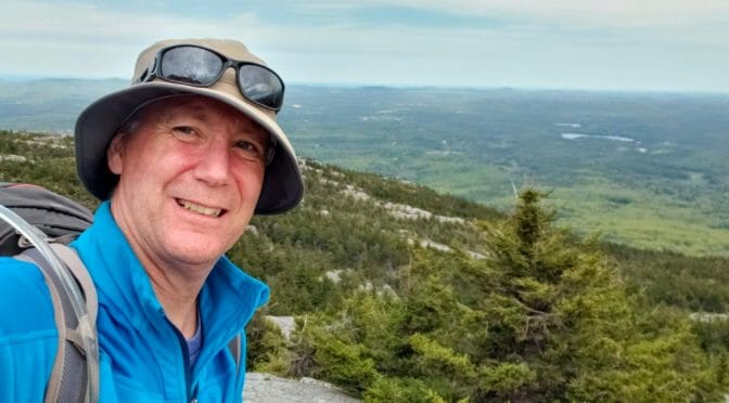
We hiked the White Dot trail on the way up. This was the shortest route up, which also meant the steepest. The advantage of the steepness was that we had beautiful views most of the way up.


Once we arrived at the top we took a quick breather and had a bite to eat before setting up our stations. Brian used a KX3 with his Buddipole mast, tripod and shock-corded whip. I used my new Buddipole shock corded mast that I got from Hamvention. John used a Xiegu 5105, which is similar to the KX2 on a crappy pole with an end-fed antenna. Mike, who is a homebrew guru came out with the Yaesu FT-817 and his home-made 6m yagi that he repurposed from his old 6m home-brew he brought to Mount Pack Monadnock.


None of us created any pile-ups while on the peak, but we all had a great time. I did make one dx call to Italy which gave me enough QSOs for a successful SOTA activation.
On the hike down we traveled the White Cross trail which was less steep and still offered some beautiful views. We were all tired by the end, but looking forward to our next SOTA event!

The club will be going up Mount Kearsarge for a SOTA/POTA activation during the ARRL’s VHF/UHF contest on Saturday, June 8th. Members can hike up the mountain or drive up and there should be plenty of activity on 6m and up!
Jamey, AC1DC