

The Nashua Area Society will be part of the fun at HamXposition @ Boxboro again this year. We will be adding some new things this year as well as providing the Ham Radio Expo display that we did last year. Our contributions will include:
- An expanded Ham Expo Display
- Ham Bootcamp – a new activity for prospective and recently licensed Technician and General Class Hams
- An Expanded Kit Building Activity
- Several Forum Presentations featuring some of our recent projects and NARS Activities leading to our recognition as Club Of The Year
We will need a lot of help from NARS members to make our contribution to HamXposition successful. More on this later in this article.
Ham Radio Expo Display
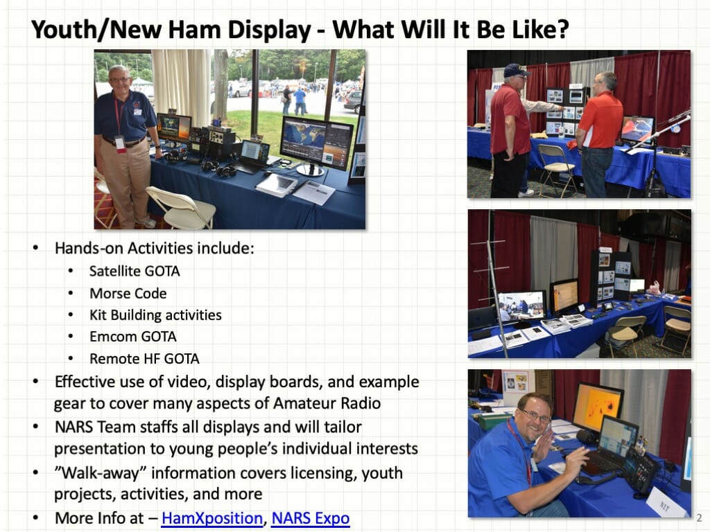
Our Ham Expo display will cover many activities that you can do with Amateur Radio. Our display will also include three GOTA stations:
- A Computer Controlled Satellite GOTA
- A Remotely Controlled High-Power HF GOTA
- A Repeater GOTA
We will also be adding a radio programming clinic where you can get your HT programmed at the show.
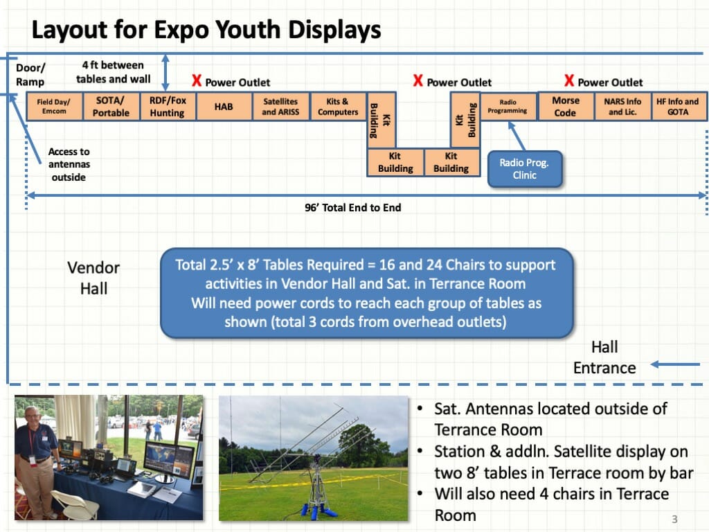
The diagram above shows the planned layout for our Ham Expo display. It will cover the entire back wall of the main exhibit hall in the vendor area and will include the Satellite GOTA station in the bar area as we did last year.
Ham Bootcamp
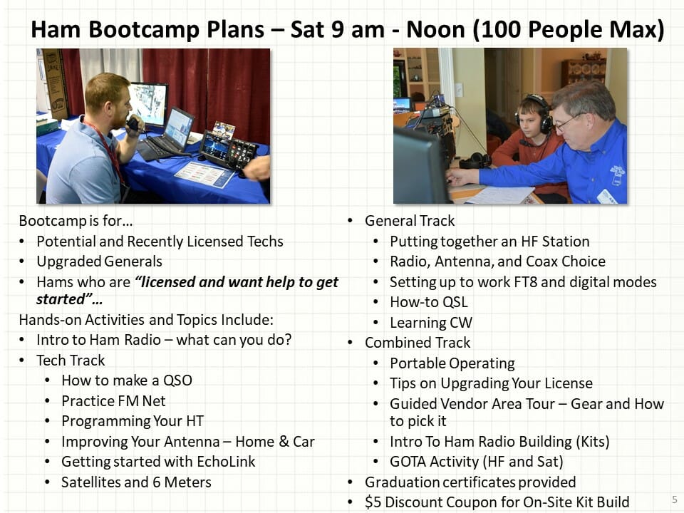
Ham Bootcamp is a new activity this year. Ham Bootcamp is a hands-on activity for folks interested in getting a Ham Radio License and folks who have gotten their Technician or General Class License and would like so help to get on the air or to upgrade their station to take advantage of their new General Class privileges. Our planned activities are outlined in the chart above. Most will be hands-on in small groups of 10 or less so we can answer questions and demonstrate how to have fun with Ham Radio. Ham Bootcamp will take place from 9 am to noon on Saturday and will accommodate up to 100 HamXposition attendees on a first-come-first-served basis. We will also provide a $5 discount coupon to all Ham Bootcampers to use toward one of the kits that are included in our kit building activity at HamXposition.
Kit Building Plans
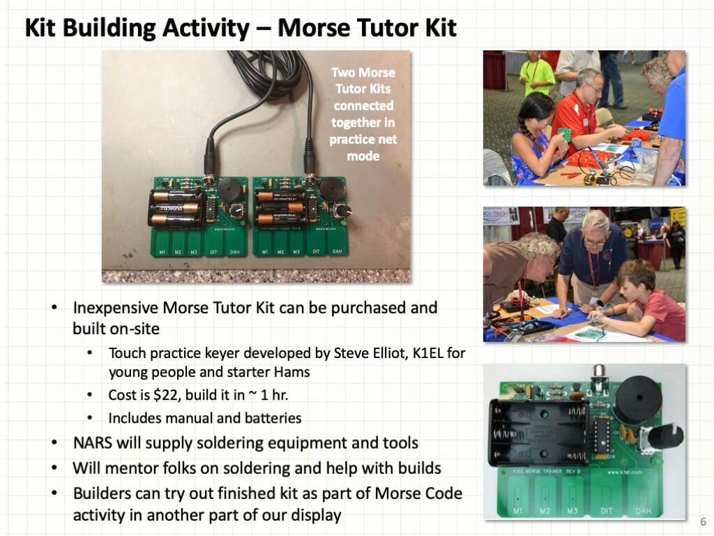
The popular Morse Tutor kit will be back again this year and we’ll have folks on hand as well equipment so that folks can build their kit and get it working at the show. You can find more about our Morse Tutor kit here.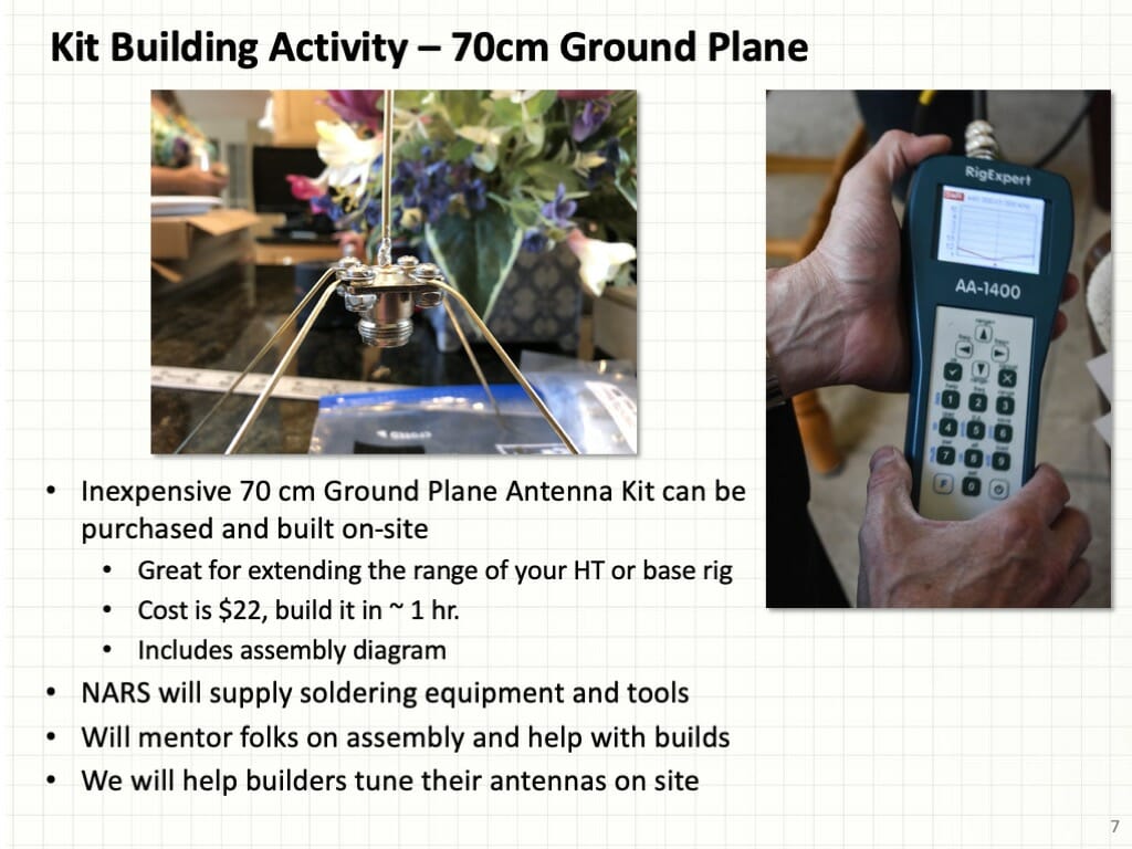
We will be adding a second kit at our kit build – a 70 cm ground plane antenna. This is an antenna that you can build and use to help your HT or base rig get out better on the 70 cm band. We’ll have an analyzer and folks who can help you to tune your antenna for the best operation after you complete your kit.
Forum Presentations
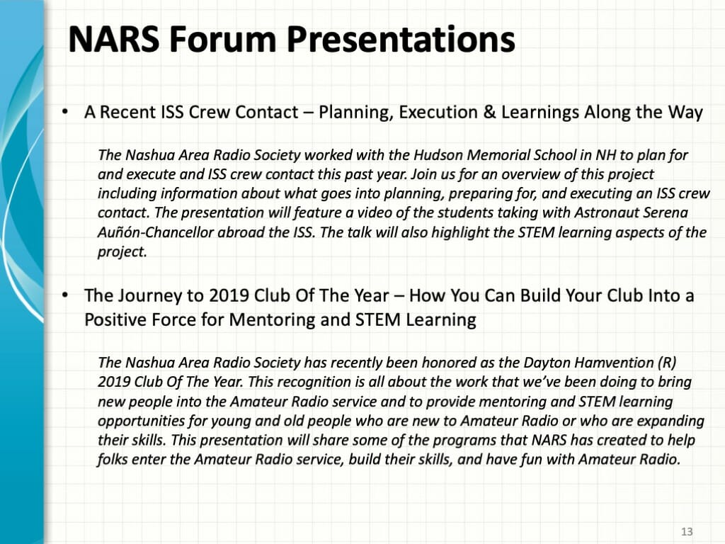
The Nashua Area Radio Society has had a pretty amazing year and we will have the opportunity to share some of our experiences at HamXposition via forum presentations. You can see the topics for our planned presentations above.
We Need Your Help
HamXposition is an important undertaking for us and for the northeastern Amateur Radio Community as a whole. We need your help to plan and execute our plans. Please reach out to Dave, Jerry, Scott or myself and join our HamXposition Team. It will be a lot of fun and a rewarding change to give back to the northeastern Amateur Radio Community.
Fred, AB1OC