
By Dennis Marandos – K1LGQ
The excitement for warm time operations is just heating up and getting out is easier now than it was a while ago. And judging from what I have already heard on the air, the rivalry for band space is getting hotter and harder to find. Let me tell you about an episode I experienced in Nashua one warm, sunny day when the adrenaline was kicking in and the sun was shining brightly. In the back of my mind-set was the sheer fact that I am radio-active, have a valid license, am getting on the air is what I love so what could possibly go wrong?
I arrived at the local city greenery named Greeley Park (after Horace Greeley) in Nashua, NH and scouted for some tall, white pines for a wire antenna. Here in the northeast, pine trees are like blades of grass…they’re everywhere. Another friend of mine, we’ll call him Mike, and I spotted a pine tree at the edge of the 150-yard field and I took aim with my trust surgical-rubber sling-shot, bought at the local Wal-Mart emporium, and on the second try landed a nice 95 foot shot into the coniferous tower. With my mighty homebrew antenna, called the ‘Gusher,’ the tentacle was placed into combat readiness within fifteen minutes after arriving at the park. We mountain men of the northeast don’t waste any time in being prepared.
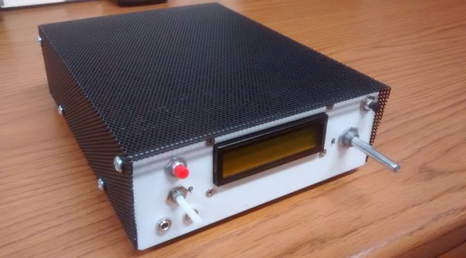
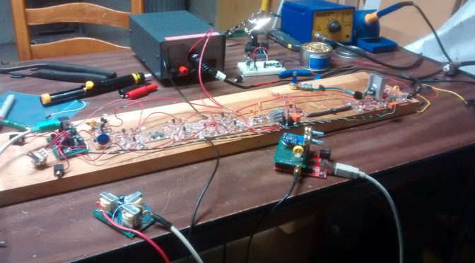
The yellow card table was unfolded, the collapsible chair was pushed into the ground for stability, and the tools of the day were unraveled. The NorCal 40a, a 40-meter homebrew transceiver, was attached dutifully to the MFJ-971 antenna tuner, which was then gingerly appended to the Gusher antenna, which culminated with a fully charged jolt of volts from the 7aH gel-cell battery. The log book was strategically placed to the right side, (I am left handed so all papers need to be in front of the writing hand and to the right. Smudges…you know.) Retractable Cross pen in hand, MFJ-24 hour clock blinking away, Vibroplex Bug (Original #2636801) adjusted, antenna swaying in the breeze—what’s left?
Contest time and the calls were loud and clear. My first contact was WA4CMI. Great, we’re getting out! Second QSO was with CH3Y (Canada), a special call for an event I’m still not sure about, dealing with the police department? I wonder if I can get a QSL or an acknowledgment from them…? My third contact was N2HMN in New Jersey, followed by KA3P in Pittsburgh, PA. It seems the RF was flowing to the north and south. The vertical long wire (a sloper) was still hanging in the tree pouring out two watts of pure, unadulterated New Hampshire power across the country…around the world. (I always like to think big.) Then another contact with K1TJ in Morristown, VA, followed by N2VPK in NY, WA4KAC in MD, W1XH in MA, K3AS in PA, N2YIY in PA, KF2HC in NJ, N1RXT on Mt. Monadnock, NH, N2SMH in NJ, AA6UL/4 in VA, W3BNB in MD, AA3LY in PA, WB3GCK in DL, K9UT in IN, KC1GS on Wachusett MT, MA, K8DSS in OH, AF3V in PA, W3GES in PA, K3TKS in MD, WK8S in MI, VE3FAO in Ont., VE3LCW in Ont., and K8JJC in MI. It was pretty exciting hearing and working all these good people on 40 meters and I wanted to thank each and everyone one of them…even the dupes.
Now, what could have gone wrong during such a brilliant contest in the park such as this? During the Saturday sunshine, while in Nashua’s public park, were also 35 to 50 fifteen to nineteen-year-old teenagers who were reenacting Dungeons and Dragons. Their crusade was to run, jump, whoop and yell it up. Okay, they were over THERE, and I was over HERE, about 150 yards apart; and we were worlds away from each other. WRONG! They wanted my space also. They wanted to “play” where I was and to see if I would notice them. Actually, they were the curious ones for many came to my table and asked, “Whatcha doin’?” while snapping their gum and starring at the QRP rig. Boys and girls who were holding duct-tape swords, mock malls and hammers in their hands, wanting to know why I was using Morse code and not a microphone. One brave young man, who looked like he needed a bath, said he had a radio too. My ears perked up and I asked him what his call was. He couldn’t remember but he was on channel 19 along with his divorced mother. “Oh,” I said and turned back to my CW.
After everyone had seen what they wanted to see, they left to conquer the world. Thank goodness for me, for now it is peace and quiet time. Well, not really. Standing in front of me, for minutes…not moving, was Patrick, a five year old boy who had no one to play with and deemed me his friend. HE WOULD NOT GO AWAY. He was inquisitive and pulled on the long wire which was connected to the MFJ-971, of which I said politely, “Please don’t touch anything.” He said okay, until he saw the cable from my gel-cell and wanted to know why it was red and black. I said politely, “Please don’t touch anything.” This appeased him until he saw inside my Xerox paper box filled with field strength meters, a frequency meter, coax, et al, something more interesting. Patrick wanted to see what else was inside and proceeded to empty, one piece at a time, the entire contents of what was there. “Wow, what are you doing?”…ran through my mind, but I looked at him and said politely, “Please don’t touch anything.” I, at this time, mentioned that his father was looking for him, or perhaps his mother wanted him too. Patrick said his mother wasn’t there in the park but that his father wanted him to play with that nice man in the corner of the field…me. My eye lit open and I said nicely, “Why don’t you go play with your friends.” He said he wanted to stay and watch me. Patrick then spied the Oreo cookies I had in my Tupperware container in my Xerox catch-all radio box. He said that they must taste good because he has had them before. I offered two cookies to him and said make sure your dad gives you permission to eat them. Patrick ran away with smiles on his face and a kick in his gait.
Patrick ran back ten minutes later, mouth all loaded with black cookie crumbs and said that they were so good he was wondering if there might be more. Again, he got another two cookies and off he went. That was the end of Patrick, until he came back for the third handout. I said, “I am sorry Patrick, but you ate them all and now you’ll have to leave here and not come back till I have over fifty contacts.” He didn’t understand what I meant but HE LEFT! Nice kid, but what a time to pick to be an inquisitive five year old!
Did I have a good time? YES! I can’t wait for the next QRP contest in the park, and I know a lot of us are waiting for the good times to continue. I have always said that amateur radio has to be instant gratification and that’s why I love it so much. This has got to be the best fraternity I’ve even been in and I love all you guys. You dudes are great and I want to work you all. And…Patrick, too!