Category Archives: Antennas

Articles about Antennas, Feedlines, Towers and related equipment. Fixed, Portable and Mobile Antenna Articles are included.

Summertime Station and Antenna Projects At AB1OC/AB1QB

Summer is the time of year that many of us work on our antennas and improve our stations. Anita AB1QB and I did both of these things at our QTH this summer.

Antenna Projects - Removing Lower SteppIR Yagi From Tower
Removing Lower SteppIR Yagi From Tower

Our SteppIR DB36 Yagis were due for some maintenance so we took them off our tower. Special thanks to all the members of the Nashua Area Radio Club who helped us remove, recondition and reinstall our antennas! Matt Strelow, KC1XX of XX Towers and Andrew Toth provided equipment and know how to safely remove our two large SteppIR DB36 Yagis with help from the rest of us.

Antenna Projects - Lowering Antenna With Electric Winch
Lowering Antenna With Electric Winch

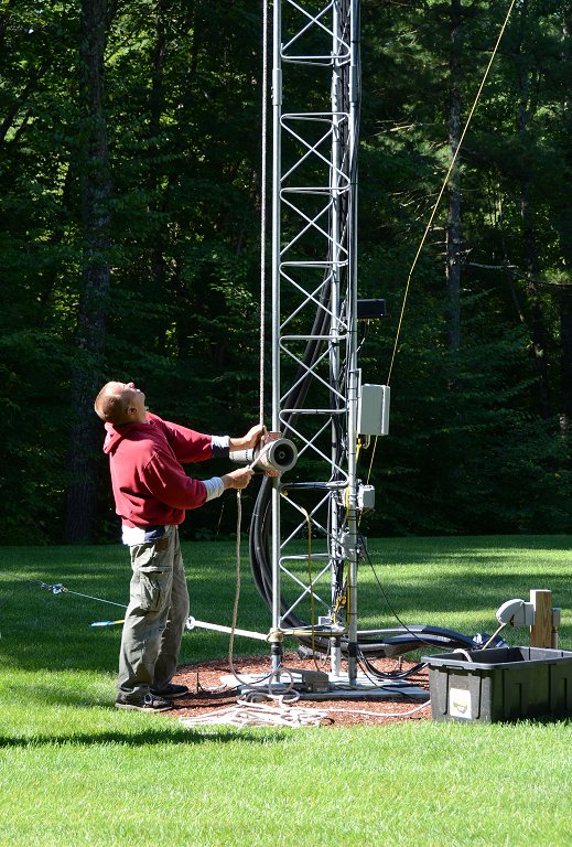
The SteppIR DB36 Yagis weigh almost 200 lbs each and Matt made good use of his electric winch to lower them.

Antenna Projects - Antenna Coming Down The Tram Line
Antenna Coming Down The Tram Line

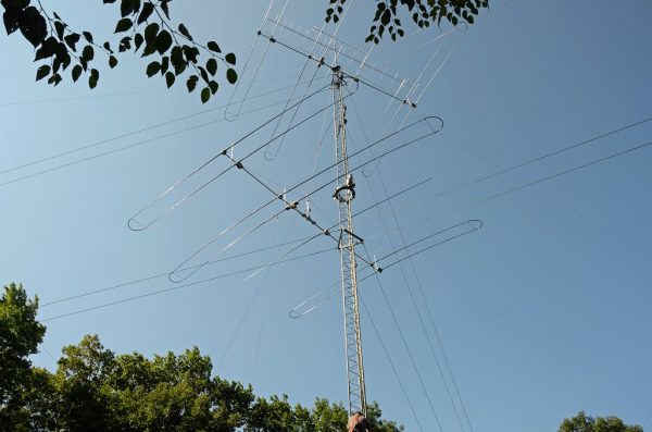
The picture above shows the lower antenna coming off the tower. We used a Tram Line system to lower both antennas to the ground so that we could rebuild them.

Antenna Projects - SteppIR DB36 Antenna On The Ground
SteppIR DB36 Antenna On The Ground

The SteppIR DB36 Yagis are quite large. They have 36 ft booms and the driven elements are almost 50 ft from tip to tip! They completely fill up our back yard when they are both off of the tower.

SteppIR Rebuild

Antenna Projects - Element Pole Sun Damage
Element Pole Sun Damage

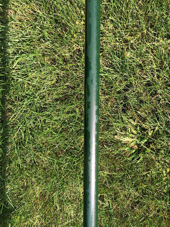
The rebuild process began with a careful inspection of both antennas. They were both in good overall condition with some sun damage to the paint on the fiberglass element poles.

Antenna Projects - Disassembled SteppIR DB36
Disassembled SteppIR DB36

We removed all the element tubes and sweeps from both antennas for rebuilding. The picture above shows the disassembled upper antenna.

Antenna Projects - Rebuilt Stepper Motors Installed
Rebuilt Stepper Motors Installed

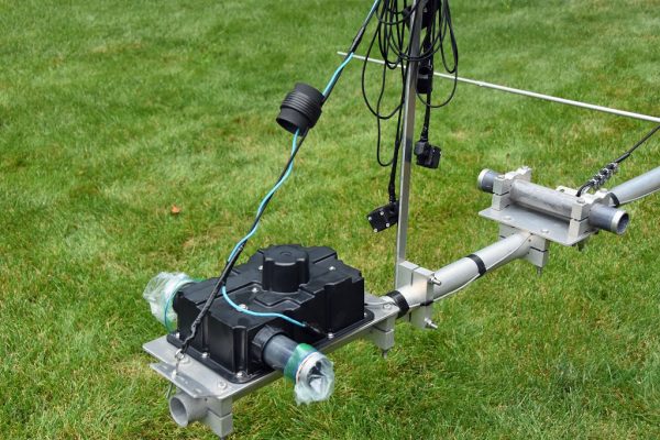
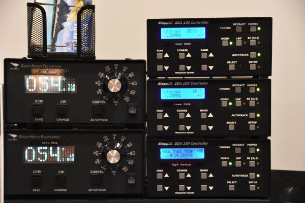
All four Stepper motors on both antennas were replaced. These motors move metal tapes inside hollow element tubes to adjust the length of each antenna’s 4 movable elements. These adjustments are done automatically by controllers in our shack which receive frequency information from the radios which are connected to each antenna.

Antenna Projects - Reconditioned Element Sweep Poles
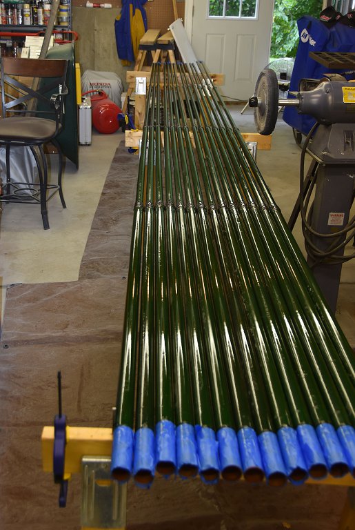
Reconditioned Element Sweep Poles

All of the element housing poles were cleaned, prepped and painted with a UV resistant clear coat to protect them from further sun damage. The poles cleaned up like new.

Antenna Projects - New Element Sweeps Ready For Installation
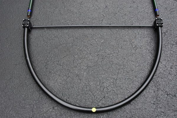
New Element Sweeps Ready For Installation

The assembly of all the new element sweep tubes (shown above) was done next. Each antenna has six sweeps.

Antenna Projects - Element Pole Preparation
Element Pole Preparation

The end of each element pole must be prepped with a tape system which ensures that the poles are seated properly, sealed to and firmly attached to the sweeps. This process and the associated assembly and tightening of the element couplers was the most time-consuming step in the rebuilding process as it had to be repeated a total of 24 times.

Antenna Projects - Rebuilt Element Assembly
Rebuilt Element Assembly

Here’s a picture of one of the rebuilt element tube assemblies. The ropes support the element tubes and keep them aligned when the antenna is up in the air. These elements are attached to the antenna motors with couplers and clamps.

Antenna Projects - SteppIR DB36 Yagi Rebuild Complete
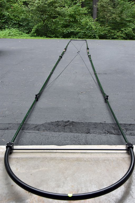
SteppIR DB36 Yagi Rebuild Complete

The picture above shows the lower antenna with all the element tubes reattached. There is quite a bit of additional prep work associated with adjusting all the supports and taping all the exposed areas of the antennas which are susceptible to sun damage. Also, all the electrical wiring on the antenna must be checked to ensure good electrical connections and good overall condition of the wiring.

SteppIR Ground Testing


Antenna Projects - Ground Test Setup
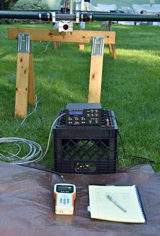
Ground Test Setup

The final step in rebuilding the antennas is to test their operation on the ground. This ground test is done to ensure that all the motors are working correctly and that the element tapes move smoothly inside the rebuilt element tubes.

Antenna Projects - Ground Test Results
Ground Test Results

Another important part of the antenna Ground Test is to confirm that the antennas have a consistent resonant frequency and SWR on all bands. The resonant frequencies and SWR levels are far from those that would be measured when the antennas are on the tower at operating height. The idea here is to confirm that a resonance exists and that its frequency and SWR readings are repeatable as the antenna is adjusted to different bands.

SteppIR Installation and Final Testing


Tramming Antennas Onto A 100 Ft Tower

With both antennas rebuilt, its was time for Matt and Andrew to return and, with help from folks from our club, reinstall the rebuilt antennas on our tower. The video above shows this process. It is quite something to see! The installation took about 3 1/2 hours.

Antenna Projects - Updated SteppIR Controllers
Updated SteppIR Controllers

The last step in the SteppIR DB36 rebuild process was to install the latest firmware in the associated SDA100 Antenna Controllers. There were some integration issues between the updated SteppIR Firmware and our microHAM system but we are getting those worked out with help from the folks at both SteppIR and microHAM.

Transceiver Upgrade


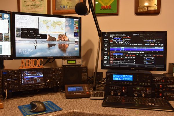
Icom IC-7851 With Display Monitor

I recently had a major birthday milestone and Anita surprised me with a new radio – an Icom IC-7851. This radio is an upgrade/replacement for our Icom IC-7800. While the two radios are quite similar in their operation and interfaces, I did not want to install the IC-7851 until the SteppIR antennas were reinstalled and all of their upgrades were working properly with our current radios. With the antennas done, it was the time to install the new radio!

Icom C-7851 Transceiver

The Icom IC-7851 has several important performance upgrades. The most impactful one is a new low phase noise oscillator which significantly improves RMDR performance compared to the IC-7800. The IC-7851 is in the top-tier of Transceivers in Sherwood Engineering’s tests. The receivers in the IC-7851 are very quiet, have excellent Dynamic Range and perform great in when close-in interference is present.

Icom IC-7851 Display Monitor

The Icom IC-7851 has a higher resolution and faster display. It also supports higher resolution external monitors so we installed an upgraded display monitor along with the new radio. The IC-7851 has a number of new networking features and supports stand-alone remote operation over a LAN and the Internet. We are planning to use these capabilities to add a second remote operating gateway to our station. More on this in a future article.

The combination of the rebuilt antennas and the new IC-7851 Transceiver has our station performing better than ever. The antennas are working as well or better than when they were new and the IC-7851 has significantly better receive performance compared to its predecessor and is a pleasure to use.

We will be hosting the ARRL Rookie Roundup RTTY contest for our club members who have received their first license in the last 3 years next weekend and we’re going to use the new radio and rebuilt antennas for the contest.

This project was completed in a little over two weeks and was a lot of work. I could not have done the project without the help of the many folks in our club. Again, a big Thank You to all the folks in our club who helped me with this project! I hope that many of you will be able to find some time to operate from our upgraded station.

73,

Fred, AB1OC

Activating Saint-Gaudens National Historical Site

We will have two club events in Cornish, NH to activate the Saint-Gaudens National Historical Site as part of the ARRL National Parks On The Air (NPOTA) program celebrating the 100th anniversary of the National Park Service.  The dates are:

  • July 10, 2016.
  • August 7, 2016.

This should give more club members a chance to operate, more HAMs a chance to make a QSO with Sullivan County, and more of the world to hear what a treasure we have in New Hampshire’s only National Park!

The park has a lot to see, and we hope that you will bring along friends and family members — even if they are not (yet!) HAMs.

The artist’s studio, his wife’s gardens, and their house (originally built as an inn in the early 1800s) should be open.  (Tickets for the house tour are free and first-come, first-served, although its hours are slightly limited on these Sundays.)  Sculpture by the artist is displayed on the grounds and in the studio.

For anyone who wants to take a break and explore the woods, there are two short nature trails (0.25mi and 1.5mi) for anyone who wants to take a break away from the radios.

This is one of only a couple of National Parks dedicated to the arts, and they have an Artist-in-Residence program, so we hope to get a chance to see and talk to a working sculptor.

The park’s new bronze cast of Augustus Saint-Gaudens’ famous 12′ statue of Abraham Lincoln will be on permanent display.  This picture of the original sculpture will give you an idea of what a monumental work of art it is:

ASG-Standing-Lincoln-finished-clay-Cornish-1886

As an added attraction, the park has concerts in July and August, following a tradition set by Augustus Saint-Gaudens.  There is no fee for them beyond the park entrance fee.  The concerts for our operating days are:

  • July 10Ensemble Amphion – Music from the Court of Henry VIII
  • August 7 – Creek River String Band – Blue Grass Music from Appalachia

The concerts will be near the studio and house, and we will be operating from the far end of the field, so there won’t be any risk of us inadvertently transmitting music and incurring the wrath of the FCC.

Concert

There are more pictures, and information on the operating conditions in the park, in the article about our trial run.

The town of Cornish also has 4 covered bridges, one of which is a National Civil Engineering Landmark.  However, not all of Cornish has been blessed with advanced Civil Engineering projects, and the NPS points out that most GPS devices and mapping software will send you over rough dirt roads to get there, so be sure to follow the directions on their website instead!

We will meet at the park to set up at 11:00 am, at the far end of the meadow/overflow parking area, away from the buildings.  The entrance to this is on the left, and it is the first part of the park that you will see as you approach it using the paved road.  The paved parking area is shortly after that, on the right.

There is no food service at the park, so we suggest packing a picnic lunch or stopping en route to eat or pick up food.  And even though Cornish is much further from the equator than Nashua, it is summer and it will be warm, so be sure to bring enough fluid to keep yourself hydrated.

Entrance to the park is $7 for those 16 and older, and there are season passes for a carload of up to 4 adults for $30.  Senior, Active Military and other special passes are available.

Aron W1AKI

A Stealth Antenna Farm

Living in a community that expressly prohibits ham radio towers often means enduring constant frustration trying to work DX with wire antennas or a multi-band vertical with what is always an inadequate radial field (read: less than 200 radials) over the “worse soil in the world”. My mantra of “work ’em on all bands and all modes” that I pursued for many years from my NH QTH has morphed to “hope I can hear them and they can hear me”. My lot can support a 40-foot tower that would be great for a small beam like the Cycle 24 used during the World Radiosport Team Championship a couple of years ago. Unfortunately, I would never get past a permit for the tower base if I ever tried to put one up.

Ah, but there is hope. The frustrations wrought by CC&R limitations often bring out the ingenuity in hams. Thanks to Layne, AE1N, I visited the website of Jeff, AC0C (see AC0C.com). Jeff lived in a condo with the no-tower restrictions. He looked over the attic where he lived and set about figuring out how to build an array of beams using the roof support structure. In a triangular volume measuring 16 feet at the apex, 20 feet long, and 40 feet wide, he managed to cram in a 22-element array that covers 160 – 6 meters! A scan of Jeff’s website is a testament to a ham’s perseverance to build an antenna farm where common sense says you cannot. Jeff used the popular EZNEC modeling program developed and maintained by Roy, W7EL. The overall configuration of the project shown on Jeff’s website looks like the proverbial rat’s nest. Somewhere on his site he mentions using over 1000 feet of coax, hundreds of ferrite cores, dozens of relays, and numerous switching boards to select the desired antenna while holding the RFI beast at bay.

Intrigued by Jeff’s work, I decided to take a look at my garage attic and see what I could do. My attic measures about 17.5 feet long, 19 feet wide, and 5 feet at the center above the floor. There is usable space beyond the garage over the remainder of the house that runs to the back, providing more depth. Unfortunately, my attic runs N-S so that any fixed antenna would have to be situated to favor a pattern to the E/NE direction for DX. I studied Jeff’s design for his 2-element 40 meter Yagi and decided to scale it for 30 meters. Each element resembles an inverted-V with the lower half of the ends bent at right angles to run horizontally along the floor of the attic. The horizontal portions of each element run toward each other so that the antenna resembles a modified “bent” Moxon antenna. (The Moxon antenna owes its design to Les Moxon, G3XN (SK). It is a 2-element beam that resembles a rectangle, is easy to build, and is forgiving in dimensions for a given band.)

I modeled the antenna with a separation of 19 feet between the elements and inserted loading coils in the driven element to shorten them. The apex height of the antenna is only about 14 feet above the ground so I was not expecting spectacular gain in the primary direction (North). The resulting pattern resembled a low dipole with maximum gain of 4.5 dB North and South, dropping to 3.4 dB at 45 degrees. While this may seem respectable, it occurs for an elevation angle of 45 degrees which means it would not work very well for typical DX angles. Indeed, when I looked at the gain performance at 24 degrees elevation, I had less than a dB. (The astute DX’er will notice that good DX performance occurs for elevation angles of 15 – 20 degrees. When limited to a height of 14 feet, the gain profile at 15 degrees is over 8 dB down from its peak.) Figure 1 shows the layout of the antenna. I realized that I’d be better off with a 30-meter inverted-V dipole off the back of the house.

Stealth Antenna– 30-meter 2-element Attic Yagi
Figure 1 – 30-meter 2-element Attic Yagi

Not to be deterred, I then modeled a 17-meter 2-element beam using relays to disconnect the 30-meter element at its coils and inserting an inverted-V element between the 30-meter elements to act as a director for 17. Figure 2 shows the results where the driven element is on the right and the director is at the center.

Stealth Antenna – 17-meter & 30-meter Attic Yagis
Figure 2 – 17-meter & 30-meter Attic Yagis

The performance for 17 meters was similar to 30 meters with a modified dipole pattern. The gain was a little better at a 24-degree elevation angle but still less than 2 dB. Again, better to stay with my inverted-V that boasts a 3.8 dB gain toward NE.

While I pondered my next move, it occurred to me that what worked for Jeff might not be the best idea for me. All that coax and those ferrite cores pointed to a lot of blood, sweat, and tears to get rid of RFI gremlins that such close quarters tend to foster. I considered using relays to change bands by lengthening or shortening the antenna elements. However, this would mean control cable wires from the shack to the antennas, themselves inadvertent antennas when transmitting. There has to be a better way.

Then, the long-dormant light bulb in my head came on. Why not try a 2-element wire beam? I looked at a model for such a beam for 17 and 15 meters, 2 elements for each band on the same “boom” and each fed separately. The results showed 17 meters behaves as expected with a gain of 6.2 dBi and a F/B of 21.6 dB. However, the 15-meter portion had a peanut-shaped pattern that was reversed from the intended direction with a F/B of less than 5 dB. I adjusted the height of the 15-meter elements within the available limits but to no avail.

Now what? I looked at the Moxon design again for its space-saving feature to see if I could get more isolation between the beams. I pulled up the file for the 2-element 17-meter beam and another file for a 15-meter Moxon beam. I merged the two antennas and juggled the positions so that the Moxon was a foot above the wire beam. Figure 3 shows the EZNEC model.

Stealth Antenna – 17-meter Beam with 15-meter Moxon Above
Figure 3 – 17-meter Beam with 15-meter Moxon Above

Figure 4 shows the azimuth gain pattern for the 17-meter beam.

Stealth Antenna – 17-meter Beam Pattern (15-meter Moxon Above it)
Figure 4 – 17-meter Beam Pattern (15-meter Moxon Above it)

Changing antennas for the 15-meter Moxon antenna produces the pattern shown in Figure 5.

Stealth Antenna – 15-meter Moxon Gain Performance
Figure 5 – 15-meter Moxon Gain Performance

As the model plots suggest, both antennas have nearly identical performance. Success at last! At least on paper minus any interactions and interfering structures such as air conditioning ducts and electrical wiring. Installing two antennas with separate feeds is easy to control with a remote antenna switch. I avoided the need for relays to shorten elements on 17 meters in order to work on 15 meters. I did not want to use relays because of the prospect of RFI causing them to trip, and the need for extra wires from my shack plus ferrite cores for RFI suppression. Now on to the fun part – BUILD IT.

Radio Amateurs Developing Skills Worldwide