Dick Powell, WK1J
A Little about me
At 75 yrs old, I have a modest station, consisting of a Mosely TA33 Tri-bander (circa 1986) on a homebrew mount, at the peak on my single-level home (45ft.) and a homebrew 160-80-40M inverted Vee at 65ft. I wound all the loading coils for the 80M and 160M traps and it performs very well and takes only 10 ft. more space than a typical 80M inverted Vee dipole (excellent for 160M on a city sized lot). I plan to write an article on its construction in the future.
I have worked 90 countries on 160M, 96 on 80M and 303 on 40M with only 100 Watts output with this antenna. I am fortunate to be at 840 ft. above Sea Level with a clear shot to Europe, South America, and the Caribbean. Japan is workable but I struggle to get through west coast stations to Asia and the Pacific. Four more confirmed countries on 80M and I will have worked 5Band-DXCC with 100W, proof that at my age, you don’t need a tower, kilowatt and the latest, greatest radio, although they make the challenge easier.
This summer I started in earnest to revamp my “small pistol” station, knowing that the sun spots are declining and that I needed to improve my low band 160m, 80m and 40M transmitting antennas. As well as my ability to hear weak signals better with the increased noise on the bands.
Latest Project: Beverages and 9-Circle Receiving Array (an article coming in the future)
This summer, I worked on improving my ability to receive weak signals by building switchable, (bi-directional) beverage antennas for NE/SW, NW/SE and E/W, switchable from my operating position. You know what they say. “If you can’t hear them, you can’t work them!”
Currently, I am in the final stages of building and deploying a 9 circle receiving array developed by the Yankee Clipper Contest Club of which I am a member. Note: The components are now offered as a kit in partnership with DXEngineering, with DXE supplying all the interconnecting cables and phasing lines. My preliminary tests show a significant improvement (8db better signal RX strength and lower noise floor by 2S units) over the beverages and it is steerable every 45 degrees. The ability to null out interference is unbelievable even when compared to the beverages. Now I need to work them! I am currently building a 160M/80M “double L”(no ground radials needed), separate 40M and 80M Delta Loops, replacing my older dipoles. I hope to have these in place by CQWW SSB later this month.
Now this Article: – Antenna Launcher
How to get these new wire antennas hung from the many tall pine trees on the property? In the past, I have used a sling shot to get dipoles up but usually only 50-60 ft. consistently.
I read with interest the recent article that Brian, AB1ZO wrote: “I can’t believe my antenna’s up!” Seeing the pictures of the method he used to toss a line over the tree got me to thinking about a better approach. I wanted something reliable, easy to use, easy to make (not buy), and portable in the woods, no electricity/batteries, no butane and spark ignitors (I would probably cause a large forest fire, hi!). In other words “a field day” type solution. I also recalled Dennis, K1LGQ’s presentation on the “potato launcher” he demonstrated at project night.
I viewed many YouTube videos and found a lot of excellent approaches. I settled on a pneumatic (compressed air) approach. I designed the antenna launcher to be very compact, most were quite long and not ideal for trudging through dense woods. By no means is this approach unique, but it is proving to be very reliable, cheap (less than $60 in materials, if purchased) and can easily reach heights of over 150ft. I use a simple bicycle tire pump (found for $25 on eBay) to fill the compression chamber. A compressed C02 air refill canister for a Paintball gun or a battery operated car tire pump would also work.
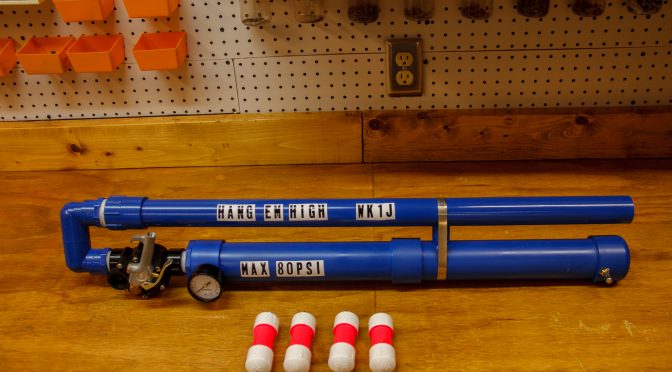
This is a picture of the completed Antenna Launcher. It took 2, 4 hour days to complete as I waited 24 hours to ensure the PVC cement cured in the pressure chamber (important safety step). I chose to spray paint it and added labeling.

I build the launcher in 4 main sections:
- Pressure Chamber
- A Modified Inline Irrigation Valve
- U section (for a compact design)
- Launching Tube
Step 1 – Pressure Chamber
I looked at both 3in. and 2in PCV schedule 40 Pipe. The box stores do not carry 3in PVC rated for pressure applications. Some videos on YouTube do use it; I chose the 2in for safety reasons (max. 280psi).
Below is a picture of the pieces needed to assemble the pressure chamber, including the tire (Schrader) valve and pressure gauge (optional). I opted to have the pressure gauge on the chamber when filling it, rather than having to read one located on a tire pump, I blame the bifocals, it couldn’t be old age!

The next 5 pictures show the progression of the assembly. For brevity, (in this article) the pictures will give you a reasonable idea of the construction. I plan to create an accompanying (downloadable) PDF document detailing all the steps with instructions.


Step 2 – In-line sprinkler Valve Modifications
This picture shows the parts needed to modify a common irrigation valve for air pressure vs electrical use. A good YouTube video of modifying the Rain Bird HD 1 in. valve can be found at https://youtu.be/A3EOdNP6Iag

The next 7 pictures show the detailed progression of the modification. They may be a little easier to see than in the video.


Step 3 – The “U” Assembly (or let’s turn the corner!)
I wanted the launcher to be as compact as possible for better portability and chose to assemble some pipe to make a “U” turn, prior to installing the actual launch tube.

The following 2 picture shows the detail of the assembly of the U-turn.


Step 4 – The launcher’s “business end” where all the work gets done…

Conclusion:
I hope I haven’t put you to sleep by now. This was a fun project and it works really well and will last for many trips into the woods in the future. There are very few mechanical parts which could fail (only the inline valve and blow gun) and the selection of higher PSI PVC ensures a good degree of safety, even if over inflated a little. The inline valve is the “weak link” so to speak, rated at 100psi max.
Now to go and “Hang ‘Em High”
73 Dick, WK1J
Questions: [email protected] [email protected]


 & 17m (bottom)")