Category Archives: Antennas

Articles about Antennas, Feedlines, Towers and related equipment. Fixed, Portable and Mobile Antenna Articles are included.

Fall Antenna Projects at AB1OC/AB1QB

Anita and I like to take advantage of the mild fall weather to do antenna projects at our QTH. We have completed two such projects this fall – the installation of a Two-Element Phased Receive System and a rebuild of the control cable interconnect system at the base of our tower.

Receive Antenna System Electronics

Antenna Projects - NCC-1 Receive Antenna System Components
NCC-1 Receive Antenna System Components

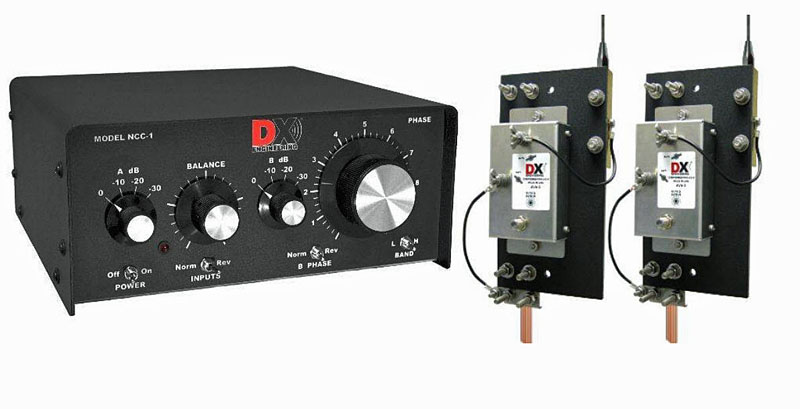
Our first project was the installation of a DXEngineering NCC-1 Receive Antenna System. This system uses two receive-only active vertical antennas to create a steerable receive antenna system. The combination can work on any band from 160m up to 10m. We set ours up for operation on the 80m and 160m bands.

Antenna Projects - NCC-1 Receive System Antenna Pattern
NCC-1 Receive System Antenna Pattern

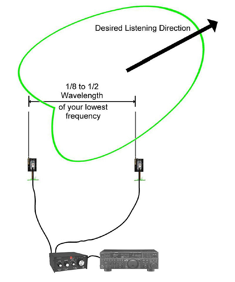
The NCC-1 System can be used to peak or null a specific incoming signal. It can also be applied to a noise source to null it out. The direction that it peaks or nulls in is determined by changing the phase relationship between the two Active Antenna Elements via the NCC-1 Controller.

Antenna Project - NCC-1 Filter Installation
NCC-1 Filter Installation

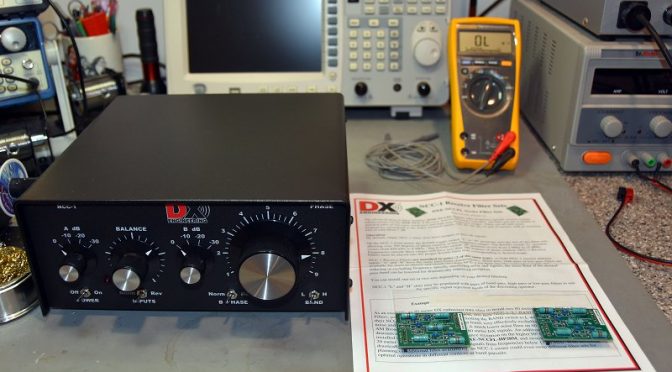
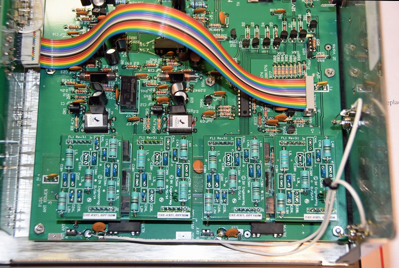
The first step in the project was to open the NCC-1 Control Unit to install a set of 80m and 160m bandpass filter boards. These filters prevent strong out-of-band signals (such as local AM radio stations) from overloading the NCC-1. The internal switches were also set to configure the NCC-1 to provide power from an external source to the receive antenna elements through the connecting coax cables.

Receive Antenna Elements and Coax


Antenna Projects - Installed Active Receive Element
Installed Active Receive Antenna Element

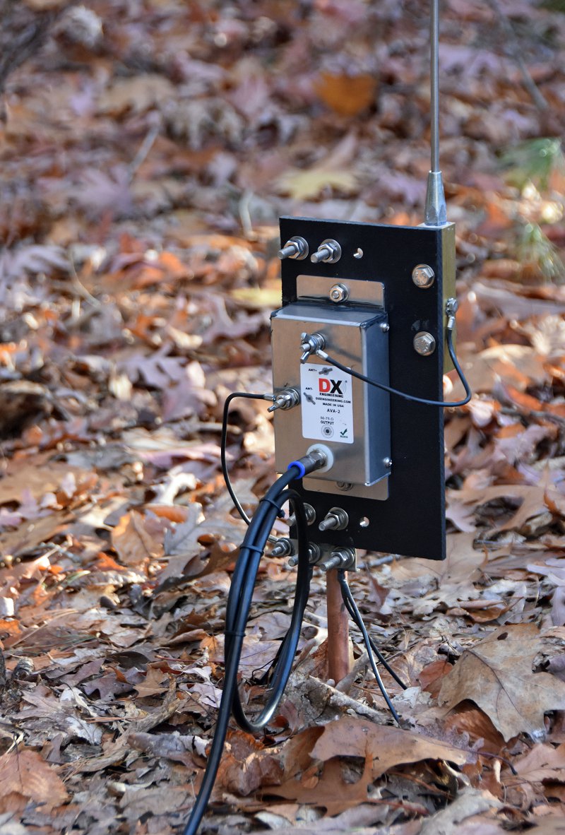
The next step in the project was to select a suitable location for installing the Receive Antenna Elements. We choose a spot on a ridge which allowed the two Antenna Elements to be separated by 135 ft (for operation on 160m/80m) and which provided a favorable orientation toward both Europe and Japan. The antenna elements use active circuitry to provide uniform phase performance between each element’s 8 1/2 foot whip antenna and the rest of the system. The antenna elements should be separated by a 1/2 wavelength or more on the lowest band of operation from any towers or transmit antennas to enable the best possible noise rejection performance.

Antenna Project - Received Antenna Element Closeup
Received Antenna Element Closeup

The two Antenna Elements were assembled and installed on 5 ft rods which were driven into the ground. To ensure a good ground for the elements and to improve their sensitivity, we opted to install 4 radials on each antenna (the black wires coming from the bottom of the unit in the picture above). The Antenna Elements are powered through 75-ohm flooded coax cables which connect them to the NCC-1 Control Unit in our shack. The coax cable connections in our setup are quite long –  the length of the pair being approximately 500 ft. The use of flooded coax cable allows the cables to be run underground or buried. Should the outer jacket become nicked, the flooding glue inside the cable will seal the damage and keep water out of the cable.

Antenna Project - RFC-1 Receive Line Choke
Receive RF Choke

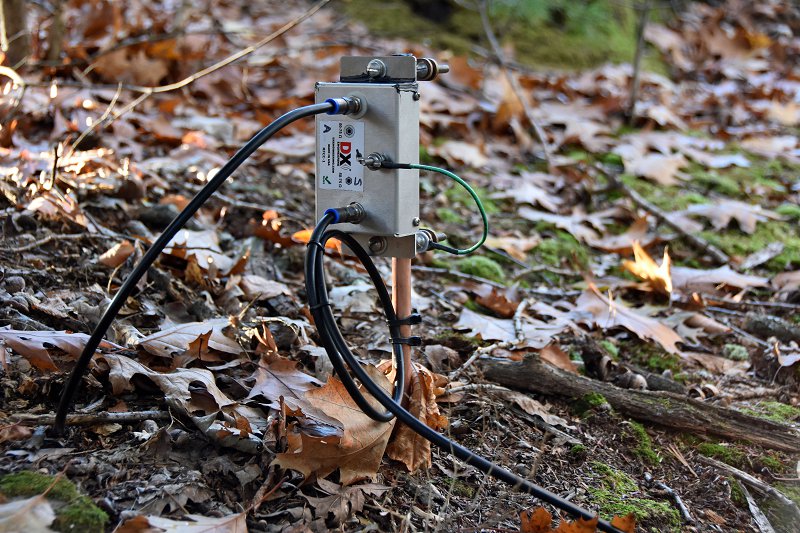
It is also important to isolate the connecting coax cables from picking up strong signals from nearby AM Radio stations, etc. To help with this, we installed Receive RF Chokes in each of the two coax cables which connect the Antenna Elements to the NCC-1. These chokes need to be installed on ground rods near the Antenna Elements for best performance.

Antenna Project - Underground Feedline Conduit
Underground Cable Conduit In Our Yard

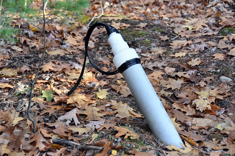
We ran the coax cables underground inside cable conduits for a good portion of the run between the antenna elements and our shack. The conduits were installed in our yard when we built our tower a few years back so getting the coax cables to our shack was relatively easy.

Antenna Project - Receive Antenna Coax Ground System
Receive Antenna Coax Ground System

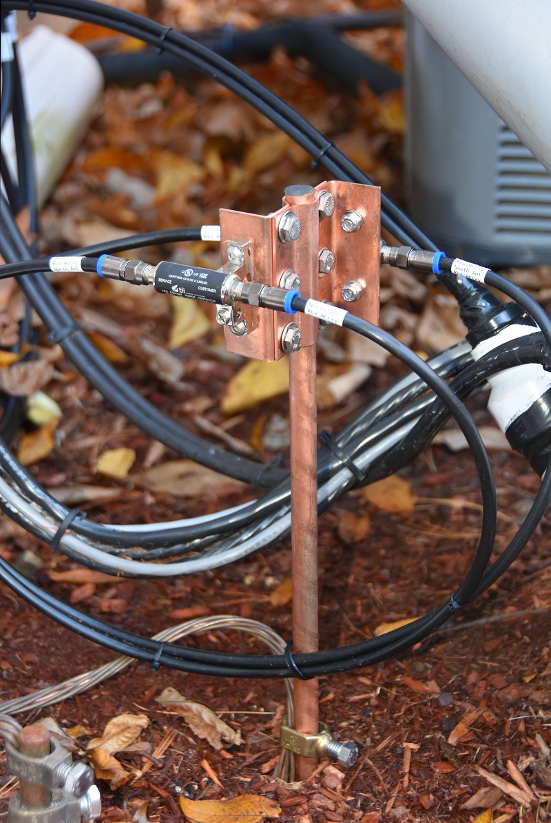
The last step in the outdoor part of this project was to install a pair of 75-ohm coax surge protectors near the entry to our shack. An additional ground rod was driven for this purpose and was bonded to the rest of our station’s ground system. We routed both of the 75-ohm coax cables from the two Antenna Elements through surge protectors and into our shack. Alpha-Delta makes the copper ground rod bracket shown in the picture for mounting the surge protectors on the ground rod.

Shack Installation


Antenna Project - Equipment Shelf In Our Shack
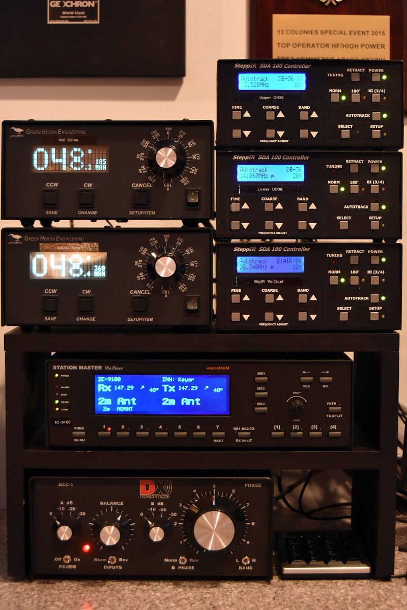
Antenna Equipment Shelf In Our Shack (The NCC-1 Control Unit Is At The Bottom)

The installation work in our shack began with the construction of a larger shelf to hold all of our antenna control equipment and to make space for the NCC-1. The two incoming coax cables from the Antenna Elements were connected to the NCC-1.

Antenna Project - uHAM Station Master Deluxe Controller
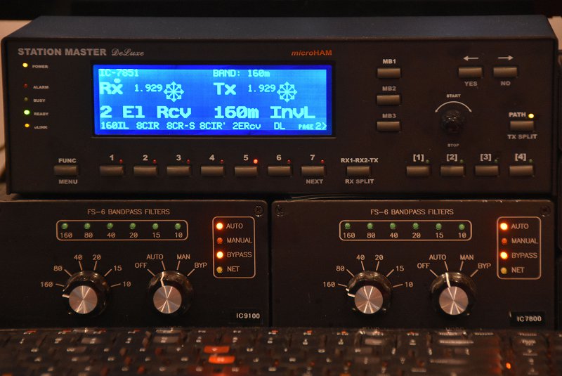
microHAM Station Master Deluxe Antenna Controller

Antenna switching and control in our station is handled by a microHAM System. Each radio has a dedicated microHAM Station Master Deluxe Antenna Controller which can be used to select separate transmit and receive antenna for the associated radio. The microHAM system allows our new Receive Antenna System to be shared between the 5 radios in our station.

Antenna Project - Switching Matrix
Antenna Switching Matrix

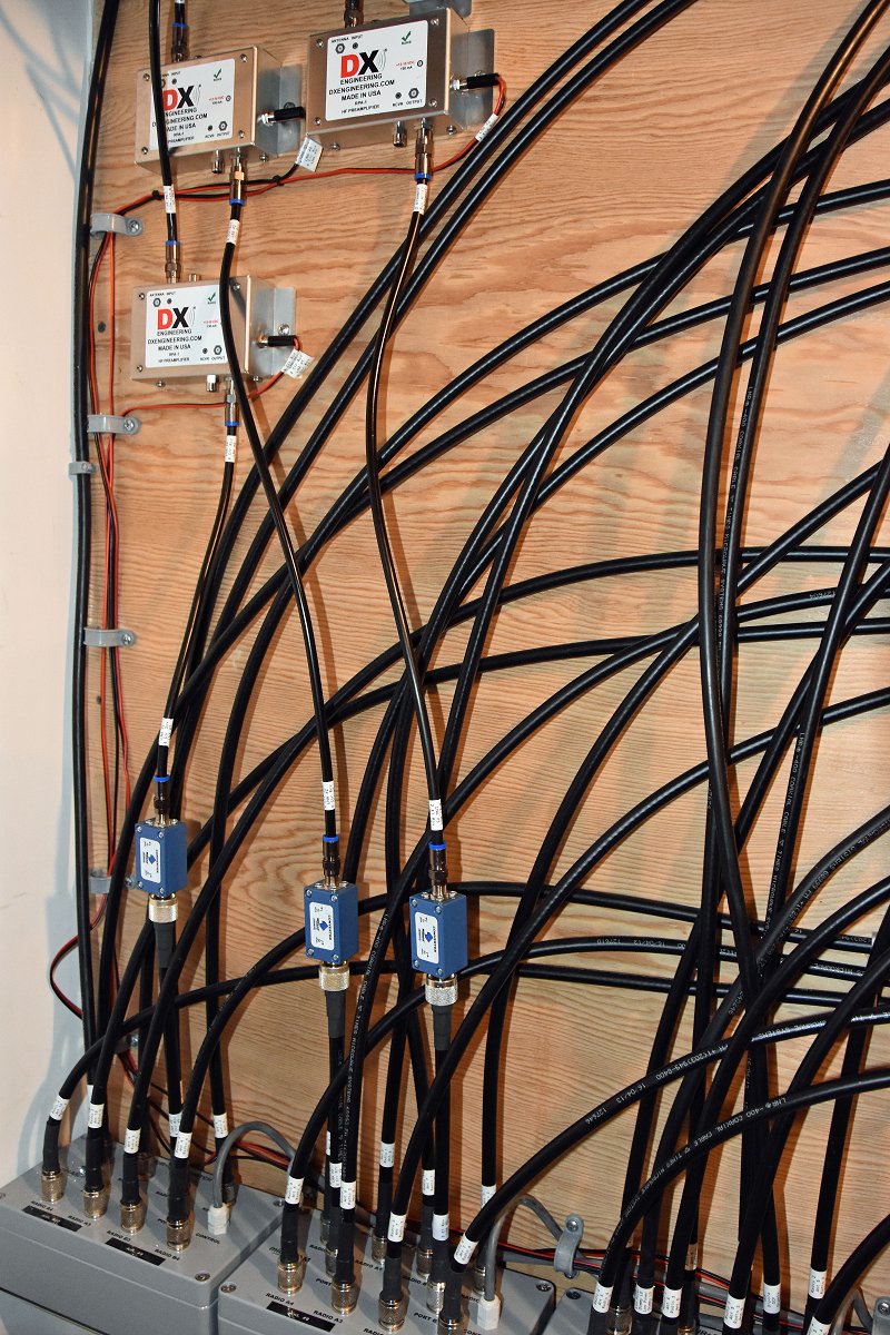
The first step in integrating the Receive Antenna System was to connect the output of the NCC-1 to the Antenna Switching Matrix outside our shack. We added a low-noise preamp (shown in the upper left of the picture above) to increase the sensitivity of the Antenna System. The blue device in the picture is a 75 ohm to 50-ohm matching transformer which matches the NCC-1’s 75-ohm output to our 50-ohm radios. The other two preamps and transformers in the picture are part of our previously installed 8-Circle Receive Antenna System.

Protection From Overload


Antenna Project - Multi-Radio Sequencer
Multi-Radio Sequencer

The Antenna Elements must be protected from overload and damage from strong nearly RF fields from our transmit antennas. In a single radio station, this can be handled via a simple sequencer unit associated with one’s radio. In a multi-op station such as ours, it is possible for a different radio than the one which is using the Receive Antenna System to be transmitting on a band which would damage the Receive Antenna System.

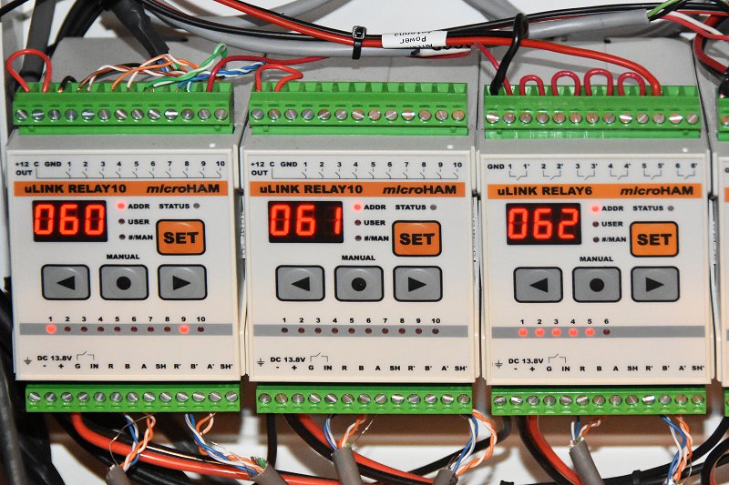
To solve this problem, we built a multi-radio sequencer using one of the microHAM control boxes in our station. The 062 Relay Unit shown above has one relay associated with each of the five radios in our station. The power to the Receive Antenna System is routed through all 5 of these relays. When any radio transmits on a band that could damage the Antenna Elements, the associated relay is automatically opened 25 mS before the radio is allowed to key up. This ensures that the system’s Antenna Elements are safely powered down and grounded.

On The Air Performance

Antenna Project - NCC-1 Controls
NCC-1 Controls

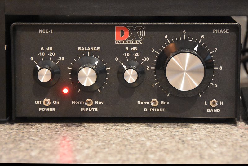
So how well does the system work? To test it, we adjusted the NCC-1 to peak and then null a weak CW signal on 80m. This is done by first adjusting the Balance and Attenuator controls on the NCC-1 so that the incoming signal is heard at the same level by both Antenna Elements. Next, the B Phase switch is set to Rev to cause the system to operate in a signal null’ing configuration and the Phase control is adjusted to maximize the null’ing effect on the target signal. One can go back and forth a few times between the Balance and Phase controls to get the best possible null. Finally, the incoming signal is peaked by setting the B Phase switch to Norm.

Antenna Project - Peaked And Nulled CW Signal
Peaked And Null’ed CW Signal

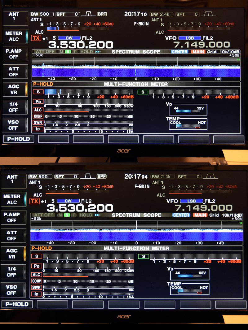
The picture above shows the display of the target CW signal on the radio using the NCC-1 Antenna System. If you look closely at the lower display in the figure (null’ed signal) you can still see the faint CW trace on the pan adapter. The difference between the peak and the null is about 3 S-units or 18 dB.

Antenna Project - Peaked And Nulled SSB Signal With NCC-1 Used For Noise Cancellation
NCC-1 Used For Noise Cancellation

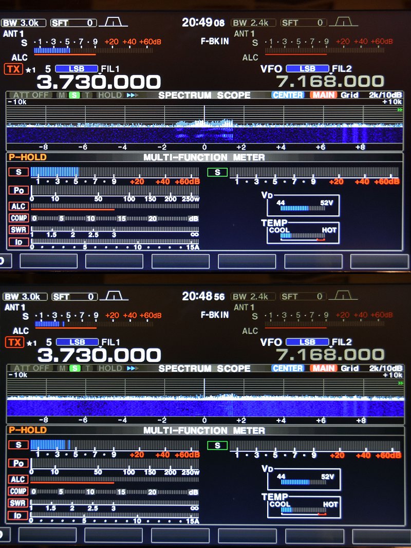
The NCC-1 can also be used to reduce (null out) background noise. The picture above shows the result of doing this for an incoming SSB signal on 75m. The system display at the top shows an S5 SSB signal in the presence of S4 – S5 noise. Also, note how clean the noise floor for the received SSB signal becomes when the unit is set to null the noise source from a different direction than the received SSB signal.

We are very pleased with the performance of our new Receive Antenna System. It should make a great tool for DX’ing on the low-bands. It is a good complement to our 8-circle steerable receive system which we use for contesting on 160m and 80m.

Other Antenna System Maintenance

Antenna Project - Tower Control Cable Interconnects
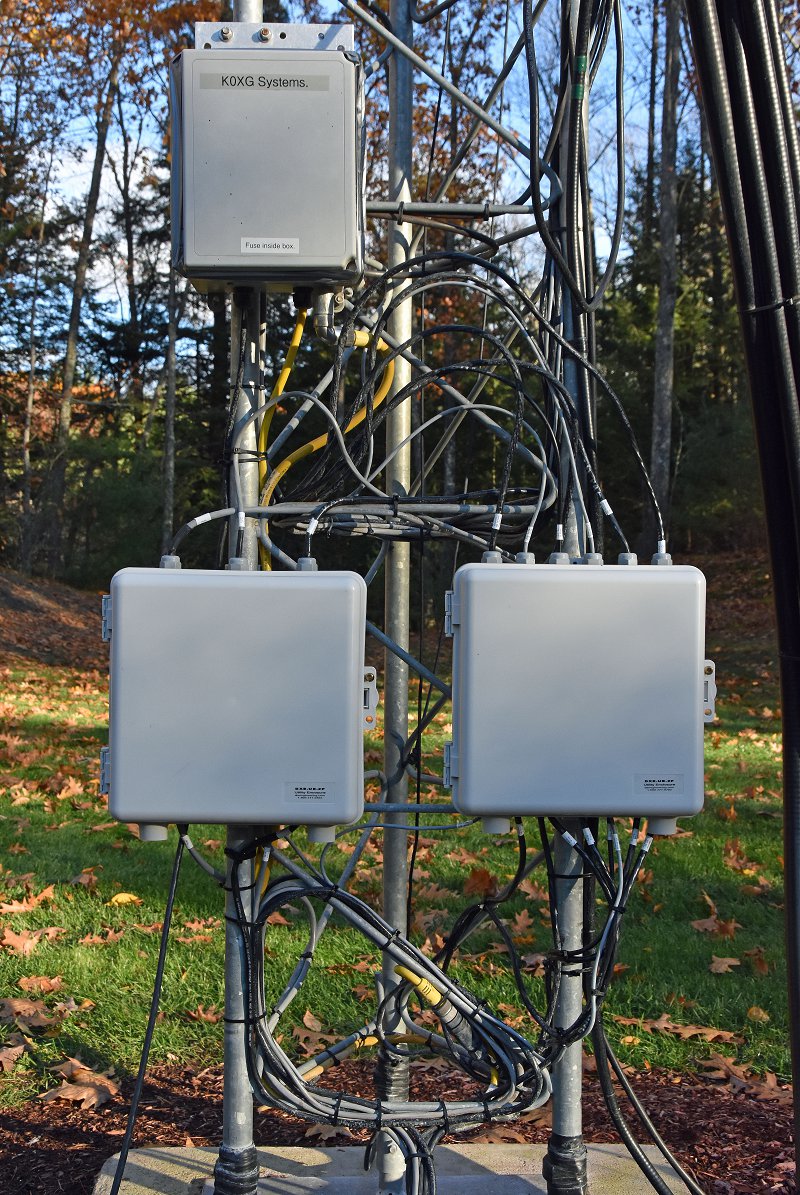
Tower Control Cable Interconnects (Bottom Two Gray Boxes)

Our other antenna project was a maintenance one. We have quite a number of control leads going to our tower. When we built our station, we placed surge protectors at the base of our tower. We then routed all of our control leads through exposed connections on these units. Over time, we found that surge protection was not necessary. Also, we became concerned about the effects that sunlight and weather were having on the exposed connections. To clean all of this up, we installed two DXEngineering Interconnect Enclosures on our tower and moved all the control cable connections inside them.

Antenna Project - Inside View Of Interconnect Enclosures
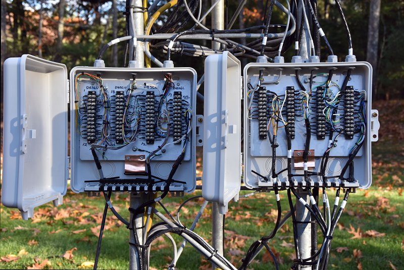
Inside View Of Interconnect Enclosures

We began with a pair of enclosures from DXEngineering and we mounted screw terminal barrier strips on the aluminum mounting plates in each enclosure. The aluminum plates are grounded via copper strap material to our tower.

Antenna Project - Closer Look At The Interconnects
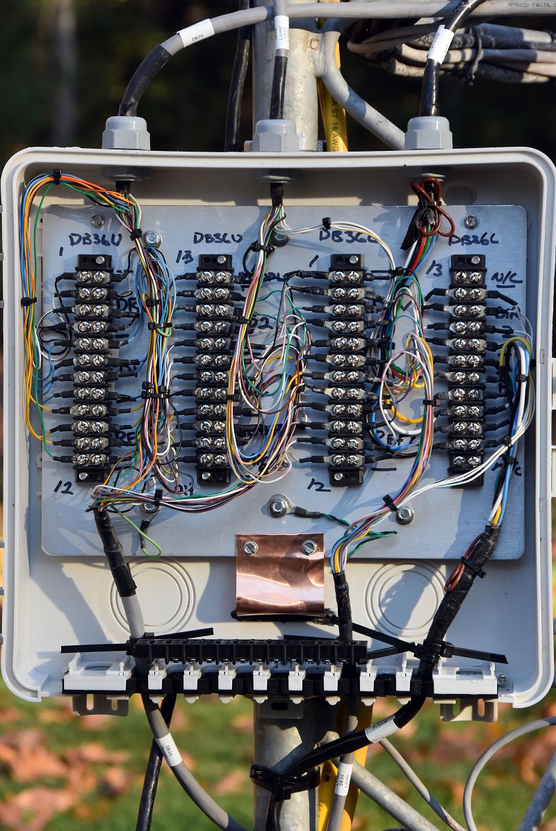
Closer Look At One Of The Interconnect Enclosures

The picture above shows one of the interconnection boxes. This one is used to connect our two SteppIR DB36 Yagi Antennas and some of the supporting equipment. The barrier strips form a convenient set of test points for troubleshooting any problems with our equipment on the tower. There are almost 100 control leads passing through the two enclosures. This arrangement keeps everything organized and protected from the weather.

With all of our antenna projects complete, we are looking forward to a fun winter of contesting and low-band DX’ing.

Fred, AB1OC

Moxons in the Attic (Part 2)

 It has been a couple of months since I wrote about my project to build a Moxon antenna for 15 and 17 meters in the attic of my garage.  The weather has since cooled down to where I can work in the attic without sweat dripping in my eyes and my hands slipping on everything.  When I wrote about my initial measurements in the last article, I was experiencing erratic SWR readings on the 15-meter beam with the lowest SWR being around 23 MHz.  I did some recomputing and figured I would need to lengthen each element by 24 inches to bring resonance down to 21.1 MHz.  I was not too thrilled with the idea of having to solder wires in the cramped space of the attic so I decided to check the SWR behavior again.

There is an old adage in carpentry that says measure twice, cut once.  The same applies for adjusting antenna elements except “twice” becomes “until consistent”.  When I connected my analyzer to the 15-meter beam, I did the flex test of the connecting cable.  Lo and behold, the SWR started jumping around.  I checked the connector hardware and noticed the PL-259 reducer shell was loose.  Once I tightened it, I found the resonant point to be way down at 19.0 MHz.  My antenna was too long; it would have to be SHORTENED by 24 inches.

Armed with the new readings, I shortened each element accordingly and measured the antenna again.  My efforts paid off with a reading of 1.1:1 at 21.2 MHz and a 2:1 bandwidth from 20.8 to 22.78 MHz.  I was now ready to move on to final installation.

I needed more coax, a couple of baluns, and a remote antenna switch to complete the project.  A hamfest scheduled for the first weekend in October in Melbourne, FL looked like a good prospect for finding what I needed.  Unfortunately, Hurricane Matthew had other plans and forced a postponement of two weeks.  When I attended the hamfest, many vendors were absent due to conflicting plans so pickings were slim.  I did manage to find the baluns and more coax but the switch would have to be ordered.

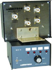
I found an Ameritron RCS-4 online at a reasonable price and ordered it.  I had used this model for many years when in NH so I was familiar with its reliability.  When the switch arrived, I hooked it up to check it out before installing it.  Murphy said hello to me with a non-functioning control unit.  I called the company I bought it from and they arranged to have it returned for a replacement.  I finally received a working unit two days before Thanksgiving.  With the CQ WW CW contest coming up, it came just in time.

I routed a 50-foot run of coax from my shack around the front of the house and into the garage attic.  Figure 1 shows the coax run.  If you can’t see it, good; I do not want the Village Vigilantes to come knocking on the door to question the aesthetics of the cable.  Figure 2 shows a closer view of the coax entering my attic.  So far, the XYL hasn’t noticed it so I’m safe.

Stealth Antenna - Coax Run Across Front of House
Figure 1. Coax Run Across Front of House
Stealth Antenna - Coax into the Attic (Upper Left)
Figure 2. Coax into the Attic (Upper Left)

The next step involved hooking up the baluns and the remote switch which was a straightforward process.  Once everything was in place, I fired up the rig on 17 meters and found a spot for UA0ZC.  I was happy to hear him and gave Val a call.  A minute later I had a rare one in the log without having to hammer away indefinitely.  I checked 15 meters and did not find much activity.  The operational SWR was a bit higher than my measurements but still under 2:1.

At least, it started out that way.  I got on the air the next day and found the SWR on 15 meters hitting 6:1 and higher.  I made a trip up to the attic to find out what was going on.  At first glance, nothing appeared amiss.  I plugged the analyzer into the 15-meter beam and noticed the SWR jumping around.  Flexing the cable made some difference but not much.  My initial thought had been some incomplete switching in the switch unit but the SWR behavior when directly connected to the analyzer ruled that out.  I tried swapping baluns between the two beams to no avail.  With other pressing holiday matters to attend to, I decided to remove a balun from the 17-meter beam in favor of the 15-meter beam.  (During my troubleshooting efforts, I noticed the 17-meter beam behaved as designed, with or without a balun.)  The 15-meter beam shows no discernible difference in performance with or without the balun.  Figure 3 shows the present feed point installation with the switch on the attic floor.

Figure 3. Feed Points and Switch

I have to admit that I am stumped at this point.  There is some consolation, however, in that my K3 tuner easily matches up the 6:1 SWR imbalance.  I imagine there is interaction with the other structures in the attic (house wiring, AC ducts, 17-meter beams, etc.) that are making a good match difficult to achieve.  At any rate, I am happy to have a worthwhile antenna for 17 meters vice my low inverted V.  As the sunspots continue to degrade, 17 meters may well end up as the MUF.

Ed, K2TE


The Nashua Area Radio Club is Number 1 Field Day Again!

We got up to some great news this morning. The Nashua Area Radio Club is once again Number 1 Field Day!!

2016 ARRL Field Day Results - 7A Category
2016 Results – 7A Category

We are the Top Club in our Category (7A) for 2016 with a final score of 9,292. The next closest club was W6TRW with a score of 5,610. You can see all the 2016 results on the ARRL score page. For a more detailed breakdown of our score for 2016, check out our Field Day page.

Congratulations to everyone who helped to make our 2016 operation a success! Also, a special thank you to our planning team –

Our 2016 Field Day Planning Team
Our Planning Team
Field Day Presentation
Mike, K1WVO Helping To Deliver Our Field Day Presentation During Our Club Meeting
Field Day Presentation
Presentation At Our Club Meeting

We certainly have many great memories from our 2016 Operation. I spent some time today looking at the photos from our 2016 Operation and the video from our 2016 Operation again. I picked out some photos to share here –

40m V-Beam
Our 40m V-Beam

Our setup was well planned and the execution was top-notch!

CW Row
CW/6m Row With One Of Two Of Our Towers And Beams
20m CW Op
20m CW Station
DATV Station Equipment
SSB Stations and Digital ATV Station on 70 cm
Satellite Station Equipment
LEO Satellite Station

Many folks in our club pulled together to build our setup and we operated hard during Field Day.

Mike, KU1V Operating During Field Day 2016
Mike, KU1V Operating
40m CW Op
Ed, K2TE Operating 40m CW
20m CW Op
Bill, NJ1H Operating 20m CW
20m SSB Op
Jamey, KC1ENX, Operating 20m SSB
75m-15m SSB Op, AB1BY
Abby, KC1FFX Operating on 75m SSB
40m SSB Ops
Brian, AB1ZO Operating on 40m SSB
Jeff, WA1HCO Operating On 6m During Field Day 2016
Jeff, WA1HCO Operating On 6m
Field Day Fun
Field Day Fun 2016
Field Day Feast!
Merle, W1MSI Provided Us With A  Feast!

We also helped to introduce folks to Amateur Radio via our GOTA Station.

Field Day GOTA Station
Our GOTA Station Provided By Wayne, KB1HYL

It’s fun to think about all the great things that went on during Field Day this year.

Our 2016 Highlights Video

Looking forward to our 2017 Field Day operation!!!

Fred, AB1OC

Hashtag: #ARRLFD

Radio Amateurs Developing Skills Worldwide