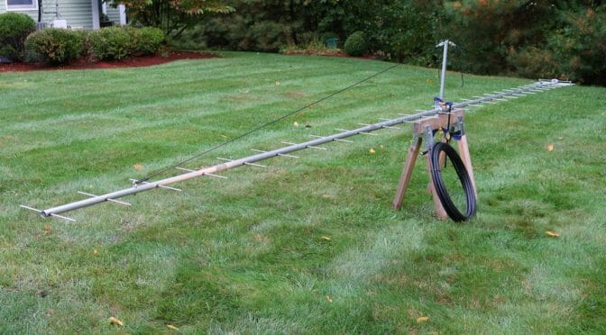
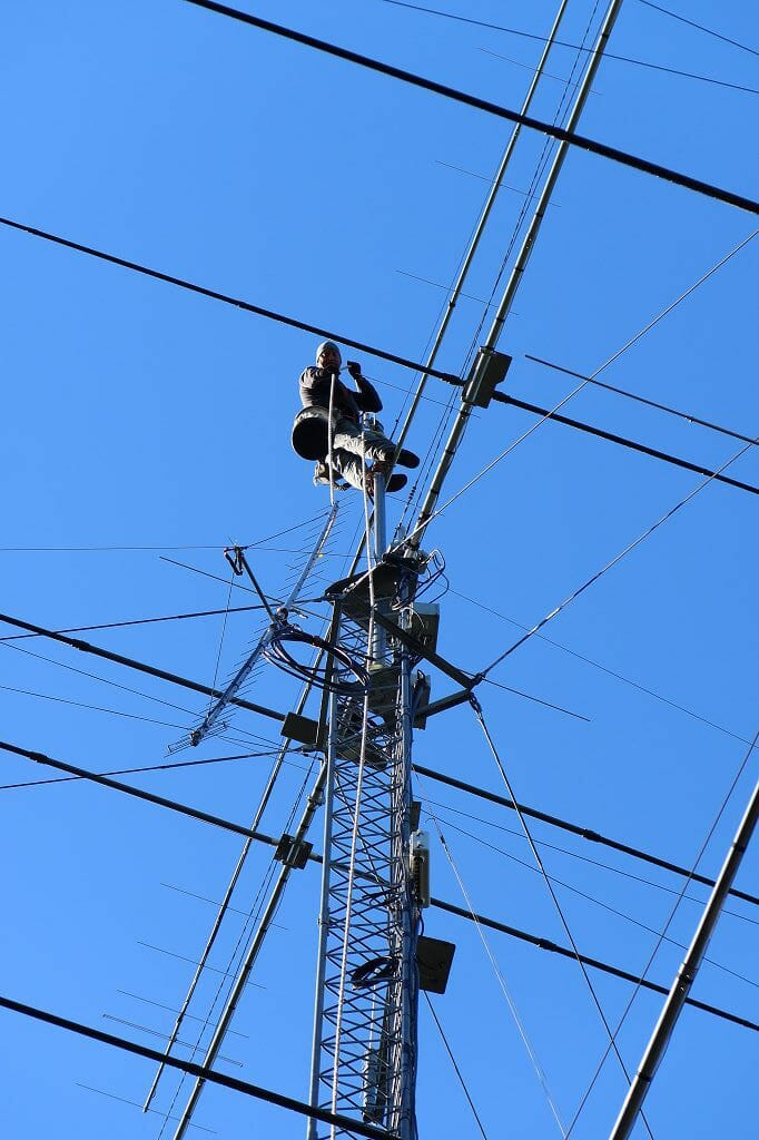
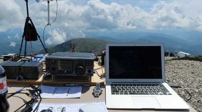
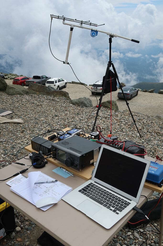
There was a query after the September newsletter was published regarding the antenna pictured in my 100 Pound DXpedition article. Here are the details.
15m 2-Element Buddipole Yagi
The standard Buddipole Deluxe kit can be augmented to produce a very effective two-element 15 meter Yagi. This antenna was used on St. Thomas, USVI, during the 2010 CQ WPX Phone contest by NE1RD to generate nearly 800 QSOs using only 5 watts (QRP). This note provides assembly instructions for this antenna.
Necessary Components
The components necessary to construct this antenna are:
- 1x ~ Buddipole Yagi converter kit
- 8x ~ 22” Antenna accessory arms
- 2x arms for the driven element
- 2x arms for the reflector element
- 4x arms for the antenna boom
- 2x ~ 11” Antenna accessory arms
- 4x ~ 9.5 fool long Buddipole whips
- Buddipole Deluxe System
- Rotating arm kit (RAK) knobs with nylon washers
- One knob holds the reflector to the end of the boom
- The other knob holds the center IT adapter to the mast
- Buddipole VersaTee
- Coax feed-line with banana plugs
- Velcro strap (and additional strapping to secure the feed line to the boom)
- 8-foot mast
- Tripod
- Guying system or very heavy weight on the bottom of the tripod to prevent tipping
Antenna Design
The basic design of the antenna is illustrated in Figure 1.

Figure 1. Buddipole 15m 2-el Yagi
Construction Details
- Begin by constructing the boom. Locate one of the IT adapters that came with the Buddipole Yagi kit. Screw a 22” arm into each side of the IT adapter. Add a second 22” arm to each side to produce a boom nearly 8-feet in length.
- Construct the reflector by locating the second IT adapter. Screw a 22” inch arm into each side of the IT adapter. Attach an 11” arm to each side of this assembly. There should be approximately 34” of arms on each side of the IT adapter. Locate two 9.5’ Buddipole long whips and, with the whips collapsed, attach a whip to each side of the reflector assembly.
- Construct the driven element by locating the threaded 3/8” x 24 threaded rod. Screw this rod into the top of the VersaTee. Attach the Yagi collar to one end of the boom. Attach the VersaTee to the boom and mate with the Yagi collar. Be sure to have the VersaTee in the same plane as the boom’s IT adapter so that the elements will be horizontal with respect to the ground when the antenna is mounted. Attach 22” arms to each side of the VersaTee. Locate two 9.5’ Buddipole whips and, with the whips collapsed, attach the whips to the ends of those arms.
- Attach the reflector to the boom by first fixing the second Yagi collar on to the other end of the boom. Then attach the reflector, ensuring it is properly aligned with respect to the boom’s IT adapter, using one of the large RAK knobs.
- Attach the feed line to the VersaTee with black and red wires going to the corresponding colored banana plug mounts on the VersaTee. Secure with Velcro straps. (Additional straps, or other means of routing the feed line back to the center IT adapter may be necessary).
- Set up the tripod and mast as you would for a standard Buddipole deployment. Guy as necessary, or weigh down the tripod with a heavy rock or other weight.
- Locate the mast collar from the Buddipole Yagi kit and attach it to the top of the mast. Use the second RAK knob to secure the antenna to the mast.
Tuning The Antenna
The lengths of the elements are such that the antenna can be tuned easily. Extend each whip to full length, then retract the outer-most section 6 or 7 inches. Make small adjustments to the reflector to tune. The author found that even guesses (no rulers) for the element lengths were good enough for creating a good match.
SWR and 2:1 Bandwidth
A properly tuned antenna will provide a good match across the band. The two plots below are from the author’s installation on St. Thomas in March of 2010 (Figures 2 and 3).

Figure 2. 15m Yagi SWR plot

Figure 3. 15m Yagi Smith Chart plot
The small green line along the real axis between 50 and 75 Ohms is the plot for the antenna. Pure resistive load, no reactance, resonant.
Results From KP2/NE1RD Deployment
The author made 977 contacts on this antenna including 808 in the CQ WPX SSB contest (794 unique stations after duplicates were removed). He worked 48 states (missing ND and WY), and 58 DXCC entities in 17 zones in just a few days of operation. All contest contacts were made QRP (5 watts)!
Scott, NE1RD