All posts by Nashua Area Radio Society

Webmaster for the Nashua Area Radio Society

10 Meter Band Opening and Sporadic E to Europe

The 10-Meter band is open today
On Tuesday (May 18 ~10:00 PM EDT) night, I was checking out the bands to see what was happening before beginning operating that night. I usually look at my Panadapter display on 10,15 and 17-meters before I settle down on 20-meters or 40-meters where I expect to see the most activity. I noticed there were some pretty strong signals around 28.385 Mhz and I listened in a bit to the ongoing QSO. Turns out there were 3 people from KY engaged in a round-robin conversation. I thought that if the 10-meter band is open I should try calling CQ myself and I moved up to 28.391 to try my luck. I called one time and one of the guys from 28.385 came up to my frequency and invited me to join in their QSO. That was Bill, he said that he saw my call on his waterfall display and it looked strong to him, so he decided to check me out. I accepted his invitation to join the group and dropped down to their frequency. They were wrapping up an extended informal QSO but were interested in hearing from me from my NH QTH. Everyone had 5/9 signals and it sounded like we were on VHF FM it was so quiet.

KY QSOs
KY QSOs

10-meter openings are unusual for me
I have only been operating on HF for the past 3 years and rarely find the 10-meter band open. I have around 8,700 QSO entries in my logbook and at that point, only 60 were on 10 meters. 23 of those are from the Nashua Area Radio Society’s Sunday HF net. Another 5 are local groundwave QSOs. That leaves around 32 QSOs on 10 meters since May 2018. I did have a few DX calls with Canada, Brazil, and Argentina in the mix, but you can see that activity on the 10-meter band was unusual for me.

My first Trans-Atlantic 10-meter QSO
The next day I put in some serious time doing landscaping projects around the house and after I cleaned up, I had 30 or 40 minutes to play radio before dinner. I made a few calls on 20-meters and was able to talk with S57DX in Slovenia, using only 25 watts. Then I took my usual lap around the bands to see what was happening and saw this on the display for 10-meters. I made a contact with MW0NLG and had a nice long QSO with Malc. He said it was his first trans-Atlantic QSO on 10-meters and I said the same for me.

10 meter Band Opening - Flex Panadapter
Flex Panadapter

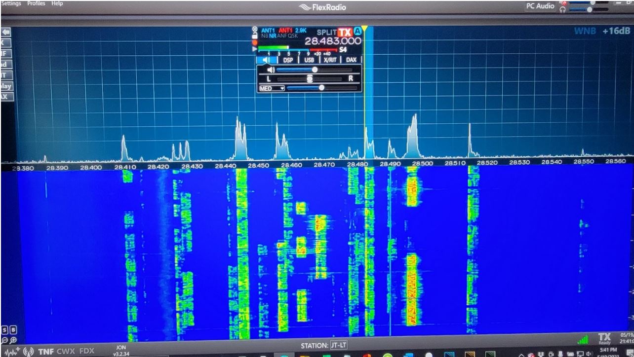
I listened in on the other signals and was surprised that they were all from Europe! My Spiderbeam antenna, which has 4 elements on 10-meters, was pointing at 52 degrees from my QSO with S57DX and I was able to hear many strong signals. I found a clear spot on the band and began to call CQ DX. I did not have any results on my first attempt but did get a reply on my second. Someone put me on the cluster at 20:24 and the pile-up began soon after.

AC1EV is Spotted on the DX Cluster

Spotted on the Cluster

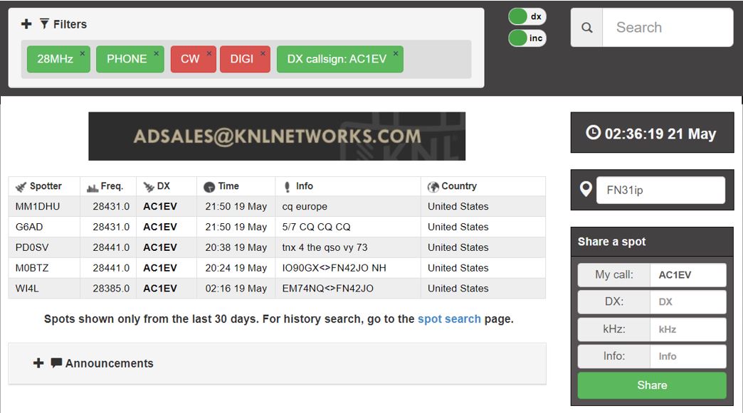
It was exciting to be able to make so many QSOs into Europe on 10 meters. I could have made more if I adopted a contest mode and just swapped signal reports, but I tried to have at least a short QSO beyond that with everyone. I also didn’t realize how unusual this opening was and when I was called for dinner, I made one last call and then went to eat. I returned after dinner and made another 4 calls before the band closed and it was done. If I experience this again, I will try and stay with the opening. Most of the calls were to Western Europe but a few were much further to the East. Bulgaria is around 4500 miles and Italy is around 4300 miles.

10 meter Band Opening - QRZ Log
QRZ Log

Conclusion
My log shows 26 calls, which is almost as many as in my whole previous ham career, in less than an hour. I had QSOs with 10 different countries, too. There is one more important thing to say about this ham adventure, all of this took place on frequencies available to Technician class license holders. You do not need more than that first license. Many of the stations I contacted were 100 watts or less and on wire antennas, so if you have a license and basic radio, you may be able to do this as well, should you encounter an opening.

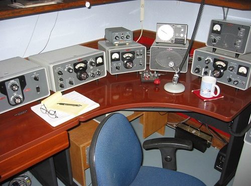
Operating conditions
Flex 6400
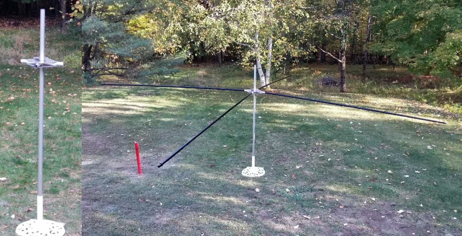
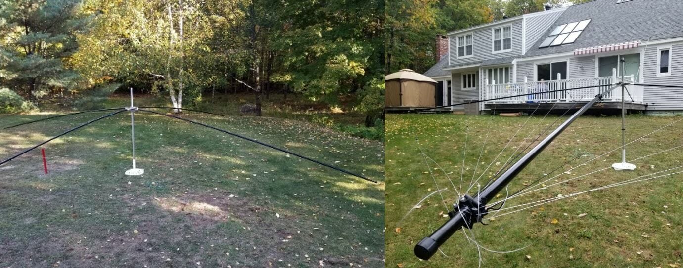
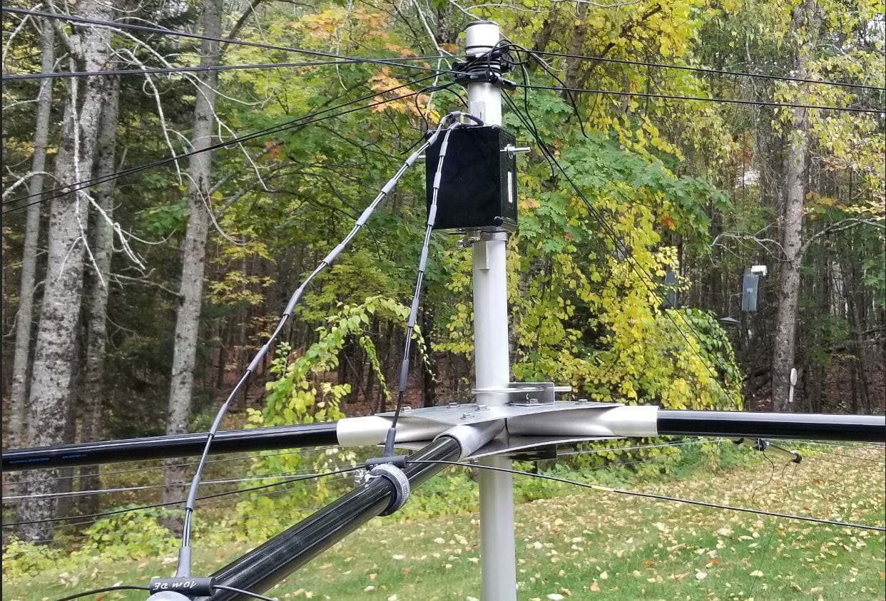
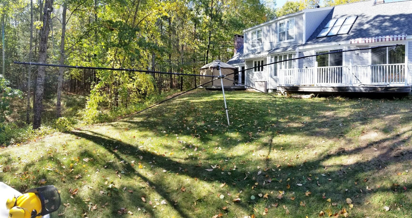
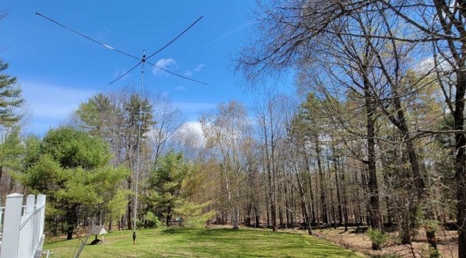
Spiderbeam with 4 elements on 10-meters @ 35 feet AGL
Elecraft KPA500 amp @ 450 Watts
QTH is on an 80-foot hill towards Europe and that couldn’t hurt a bit.

Sporadic E Definition
Many people smarter than I have written about Sporadic E Propagation. Here is a basic summary from Wikipedia for those unfamiliar with it:

Sporadic E or Es is an unusual form of radio propagation using characteristics of the Earth’s ionosphere. Whereas most forms of skywave propagation use the normal and cyclic ionization properties of the ionosphere’s F region to refract (or “bend”) radio signals back toward the Earth’s surface, sporadic E propagation bounces signals off smaller “clouds” of unusually ionized atmospheric gas in the lower E region (located at altitudes of approx. 90 to 160 km). This occasionally allows for long-distance communication at VHF frequencies not usually well-suited to such communication.

Communication distances of 800–2200 km can occur using a single Es cloud. This variability in distance depends on a number of factors, including cloud height and density. MUF also varies widely, but most commonly falls in the 25 – 150 MHz range, which includes the FM broadcast band (87.5–108 MHz), Band I VHF television (American channels 2-6, Russian channels 1-3, and European channels 2-4, the latter no longer used in Western Europe), CB radio (27 MHz) and the amateur radio 2-meter, 4-meter, 6-meter, and 10-meter bands.

As its name suggests, sporadic E is an abnormal event, but can happen at almost any time; it does, however, display seasonal patterns. Sporadic E activity peaks predictably in the summertime in both hemispheres. In North America, the peak is most noticeable in mid-to-late June, trailing off through late July and into early August. A much smaller peak is seen around the winter solstice. Activity usually begins in mid-December in the southern hemisphere, with the days immediately after Christmas being the most active period. Link to Wikipedia Sporadic E propagation – Wikipedia

Jon, AC1EV

Vintage Radio Dreamin

When I was first licensed in 1957, Collins was king of the hill in amateur radio equipment.  Collins pioneered the practical application of SSB to both military and amateur radio communications and SSB was state of the art in 1957.  The Collins S-line was just coming to market and I so wanted this gear over the 10 years I was active (1957-1967).  (The S-line was in production from the late fifties to the early eighties.) However, as a very poor kid at the beginning of this 10 year period and a poor college student at the end, personal finances made this a no-go situation. When I returned to amateur radio in 2017, I resolved to relive to some extent the good old days from the fifties and sixties and was in a position to do something about it as 50+-year-old Collins gear is much cheaper today, adjusted for inflation, than it was then. IOW, a 75S-3B receiver sold for about $600 new in 1970,  equivalent to about $4200 today, and sells today on the used market for about $600 in today’s dollars. So, I set out to find both the Collins and E.F. Johnson gear I would have given an arm for back in the day. I carefully researched the market for this Vintage Radio gear and when the opportunity presented, acquired a few of my favorites.

Vintage Radio
Collins S-line @ K8EZB

The Collins gear (75S-3B receiver, 32S-3 transmitter, KWM-2A transceiver, 30L-1 amplifier, 312B-4 station control, and 516F-2 power supply) was mostly working (the seller said) but was unrestored. It had been serviced 20 years previous by Dennis Brothers, a well-known Collins guru, and former Collins S-line production technician, but had been very little used by the seller and had been stored for at least 10 years. With this recent history and taking into account, these radios are 50+ years old, I decided to do some restoration work and updating before putting these on the air. Some of this work I did myself, but I  lacked the knowledge, skills and equipment to do everything necessary. I had, by coincidence, at about the same time developed an online friendship with Dave Harmon, K6XYZ, through the Collins Collectors Association (CCA) forum. Dave is a Collins S-line guru and offered to take on the task of checking out and updating this gear as appropriate to make it a useable, reliable station. In early 2018, I packed this equipment to withstand a thermonuclear event and shipped it off to Dave in Sperry, OK. He installed new tubes (including substituting 572Bs for the 811As in the 30L-1 amp), new power supply boards in the Harbach style, replaced capacitors and resistors where necessary, did a comprehensive alignment, and tested as a station on the air. Dave turned around these repairs quickly and shipped the equipment back to NH where it sat on a shelf in my shop until recently.

After setting up and using a thoroughly modern station for a couple of years, as a diversion from the Covid mess and from DC (District of Confusion) politics, a few weeks ago I decided to get this gear back on the air. Despite Dave’s excellent work, a few gremlins had crept in which required some troubleshooting and minor repairs. Using a vintage EICO tube tester I had acquired and restored a few years ago, I was able to trace the problems to two bad tubes which were easily replaced. I also had to deal with a steep learning curve since I had not previously used a Collins transmitter and had not tuned a tube transmitter and amp since about 1965. Fortunately, the manuals, service bulletins, and much other useful information are available online at the  CCA website. Also, many parts (new, NOS, and used) are available from multiple online sources, especially tubes, as this gear was used extensively by the U.S. military and there are large quantities of surplus NOS mil-spec tubes available at very reasonable prices. The exception regarding tubes is the  30L-1 572B final amplifier tubes which are now being made only in China and vary greatly in quality; a U. S. company,  RF Parts, is importing, testing, and creating matched sets of these tubes, so adequate replacements are available at somewhat premium prices but are not unreasonable given current prices of other transmitting tubes from that era.

Vintage tube transmitters typically require high impedance microphones. To meet this requirement, I added a Heil Gold Elite Vintage mic to the station. This mic is a wide range low impedance dynamic mic with an on-board impedance matching transformer and is intended specifically for use with vintage tube gear.

So, after a few days of preliminaries (repairs, tuning into a dummy load, monitoring transmit signal, generous coaching via email by Dave Harmon, etc) I checked into a 40m net. Success! Excellent signal reports including some reports of “fantastic” audio. The 32S-3 transmitter uses a Collins 2.1 kHz mechanical filter to determine the transmit bandwidth, with no adjustment possible, unlike modern DSP-based transceivers which typically offer several BW choices, most wider than 2.1 kHz. I have by now made quite a few contacts with this station and continue to get excellent reports including a few S9+25 reports from  NJ and VA-based stations. Out of curiosity, I have decided to add some W2IHY  outboard audio processing gear to see if “fantastic” can be made even better. I doubt this will be the case given the narrow transmit bandwidth, where audio equalization may offer little benefit. However, this gear does also provide for adjustable audio compression, which, when added to the designed-in 10 dB compression in the Collins RF circuitry, may increase average power. We’ll see. In any event, this outboard audio gear will be more beneficial with the older vintage gear coming next. The 30L-1 amp is spec’d at 1000 watts DC input (nominally 500mA at 2000 volts) which translates to about 600 watts PEP output. I have added a modern CleanRF demodulator and RF sampler to the station to allow monitoring of the transmit signal for flat-topping and linearity using RF envelope and trapezoid patterns on a vintage Tek 485 scope. So far, all is working well, and this has been a great learning/refresher experience. Quite a contrast vs my FTDX-101MP and Acom 1200S modern station!

Vintage Radio
EFJ Pacemaker
Vintage Radio
EFJ Thunderbolt

Next up in my vintage radio adventures is substituting a Collins KWM-2A for the 32S-3/75S-3B combination. This should be an easy transition as the KWM-2A is essentially a 32S-3 and 75S-3B in one box. Then, something more challenging. Waiting on the shelf is a Collins 75A-4 receiver and Johnson Pacemaker transmitter,  Thunderbolt amp, electronic TR switch, and KW Matchbox. This gear is from the generation preceding the Collins S-line and is a bit more primitive. The 75A-4 was restored a few years ago by Howard Mills, W3HM, another very well-known Collins guru (now reportedly retired from guru’ing), and the EFJ gear was restored by  Chuck Hurley, K1TLI. Both of these guys are master craftsmen and their restorations are works of art (at least to some of us!). The Thunderbolt amp weighs 120 lbs so I am hoping I can move it to the station bench.

I suspect many NARS members were born after this gear went obsolete, and will find this topic of limited interest. However, for some of us old-timers (never thought this term would apply to me!) who were into amateur radio when this gear originally came to market, pretty cool stuff!

Rick, K8EZB

AC1EV Spiderbeam Part 1 – Building the Antenna

Part 1, Building the Antenna and Base

Spiderbeam 5 Band HD Antenna

HD Spiderbeam Specifications

As shown in the specifications above the Spiderbeam has a 33-foot boom, so I measured carefully to find the best spot to build it and raise it on the mast.

Measure the site to locate the best place to install the mast.
Survey

Preparing the base for the mast

The Yaesu 800DXA Rotator that will rotate the mast and antenna will be mounted to a steel pipe buried and cemented into the ground.  The next step is to dig the hole.  The maximum reach of this post hole digger is around three feet.

Preparing the hole
Preparing the hole

Next, place the pipe in the hole and make sure it is vertical.

Set the Pipe
Set the Pipe

Add about 6 inches of gravel to the bottom of the hole to promote drainage, then add dry quick setting concrete to a few inches below the top of the hole.   Slowly add water to the dry mix and give it time to soak in.  One bag was sufficient.

Add Cement and Water

After adding water to the cement, I saw it was not draining very quickly.  I had the inspiration to use my palm sander, without any sandpaper, to vibrate the pole.  It worked great and you can see how the water level dropped and the bubbles coming out of it.  I am confident this made the concrete stronger.

Set the Cement
Set the Cement

Read the Manual Before  Antenna Assembly

While I wait for the concrete to cure properly, I will construct the antenna.  The Spiderbeam antenna packs into a compact box. The mast is a Spiderbeam 14.5 Meter HD model and is rated for full height with this antenna.  The 14.5 Meter HD telescoping mast has 9 sections.  Each section is around 6 feet long.  When fully extended it is 47 feet long.  Assemble the antenna directly onto the topmost section of the mast.

Antenna Box and Mast

Spiderbeam includes a printed booklet with detailed assembly instructions and you can also download a PDF with the latest version of instructions from their web site.  They will also provide plans to construct it yourself if desired.  After assembling their kit I can say that building this from scratch is a challenging project.  The components they provide are of high quality and worth the money.  I highly advise everyone to read the assembly instructions over at least twice before beginning work.  The manual includes instructions for the user who builds from scratch and also from the kit.  It covers the portable as well as the HD versions of the antenna.  Even after reading the instructions twice myself I still had to backtrack a few times to complete the assembly properly.

Beginning  Antenna Assembly

Open Box and hub
Open Box and hub

The box contains 20 fiberglass tube segments along with all the other parts required to assemble the antenna.  I purchased the optional Kit Assembly Service from Spiderbeam where they manufacture the wire elements, guy lines, balun, etc. This is very worthwhile and quite a time saver.  The two spools of wire shown above include all the reflectors, directors, and driven elements accurately measured.  The wires on the spools are in the correct order of use.  This makes it simple to access the next wire needed when assembling the antenna.  The wires are accurately measured, but they are not precisely tuned.  Do this once the antenna is fully assembled and off the ground a bit.

Hub and Sleeve Detail

The pictures above show some detail of the Spiderbeam Center Joint.  Where the bolts go through the tubes there is a sleeve to install in the tube to prevent it from collapsing when you tighten the bolts.  It takes some finesse to align the parts.  I used a very long nose needle nose pliers to hold the sleeve in the tube during assembly.  It is even more tricky when attaching the brackets on the top and bottom of the hub as many pieces need to be stacked up and aligned before you can insert the bolt through the sleeve.

Installing the Spreaders

Hub and Spreaders
Hub and Spreaders

To aid in the assembly I placed the topmost section of the mast into a garden umbrella holder.  Spiderbeam specifies that you install the hub 50cm from the top of the mast.  I found this to be a bit short and will make an adjustment in the future to make it 65cm.  This will give the top support guys more leverage for the spreaders. There are intermediate detailed steps as each component is installed.  The instructions keep it on track.

Installing the Wires

Spiderbeam Reflectors and Directors
Reflectors and Directors

The next step is to add the Reflectors and Directors.  I found it useful to have the antenna up high enough that I could easily duck under the wires as I put them on and adjust them.

Spiderbeam Balun
Balun

Before installing the driven elements install the balun on the mast.  There is a terminal label for each driven element.  Left and right sides are identified on each element and it is important to orient them correctly when connecting them to the balun. After this, install the wires in the order shown in the manual.

Completed Spiderbeam

Finally, I picked up the completed antenna and moved it out of the way so I would have room to work on the next phase, raising the Spiderbeam.  It weighs about 30 LBS. including the mast.  It is certainly the largest single item I ever lifted and moved.  There is lots of inertia to manage, but with care, I moved it easily.  You can see how large the antenna footprint is with it on the ground.  This is the end of Part 1.  Part 2 will be coming soon.

Jon, AC1EV