The most important piece of equipment in ham radio is our antenna. We are connected to the world with the magic of radio waves! Each License Exam from Technician through Extra class has questions to test our knowledge on antenna design and building skills. Home-brewed antennas are easy and relatively inexpensive projects.
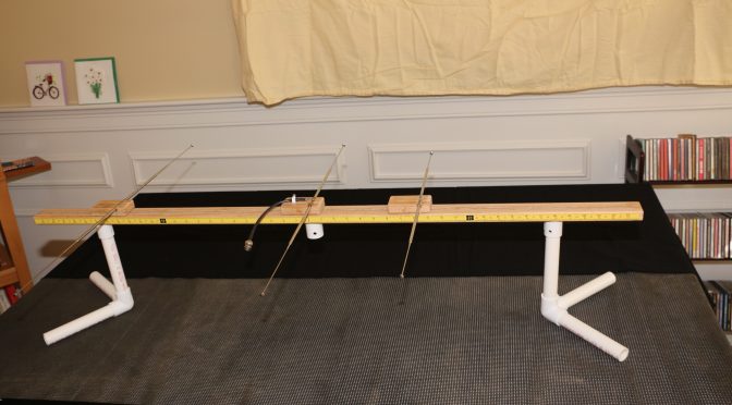
This article describes a 2m, 3-element Yagi antenna construction concept that the N1FD FCC license teaching team has used over the last year for class demonstrations. The “Lego” style construction (v. 2.0) shown in the above picture is our new design that demonstrates the operating principles of the ubiquitous basic dipole antenna as well as a 2-meter, 3 element Yagi. (Note, This project evolved from an earlier effort by Diana Eng at Makezine.com, which can be seen here.
In this Newsletter issue, we will describe the construction of the “Lego” stylized antenna and show how it can illustrate basic properties of a dipole antenna. We will build a Yagi antenna with the addition of reflector and director arms in a future Newsletter article.
CONSTRUCTION of the LEGO STYLIZED ANTENNA.

The antenna demonstration unit consists of two assemblies.
- A handheld receiver dipole set to a fixed frequency (e.g., 146.550 MHz). It is shown at the top of the photo above. It follows a “plumber’s delight” construction using pieces of PVC pipe for a short boom and handles. The dipole arms are two telescoping (7-28 inch) FM radio replacement antennas, available on eBay or Radio Shack ($4-6 dollars). The arms feed through the boom and are epoxied. Bridging across the arms is a common 6-volt flashlight bulb. The bulb lights up when the dipole receives a resonant rf signal.
- The “Lego stylized” Yagi antenna components are shown below the receiver unit. The boom (middle item) is made of red oak dimensioned at ¾ x 1 ½ x 48 The top surface is grooved to hold an epoxied 3/16 steel rod. The bottom surface has drilled recesses to fit ¾ in PVC pipe for leg stands. The edge of the boom has two 24-inch adhesive tape rulers running from center to front and back of the boom. The rulers read-out the spacing between the driven dipole element and the parasitic reflector and director arms. In the photo, the D.E. and parasitic elements are seen below the 48 in. boom. The center element is the driven dipole and it is flanked by identical units that can be configured as either reflectors or directors. Each unit consists of two telescoping FM radio antenna rods epoxied in a grooved piece of red oak ( ¾ x 1 ½ x 3 inches) serving as “riders” on the boom. The telescope arms can be adjusted to “resonance” at any frequency in the 2-meter band. The bottom of all riders has 2 x ½ inch rare earth magnets. These allow the three antenna elements to be fixed at any position on the 48 in. boom.
You can view a closer look at the assembled Yagi antenna configuration in this video (Click on Link)
DEMONSTRATIONS OF BASIC DIPOLE BEHAVIOR.
1. Antenna Resonance Determined by Dipole Length.
As we all know, the resonance length of a dipole is given by the equation: L (in inches) = 5616/ [ Frequency (in MHz)]. We can show this fact with aid of the “receiver” antenna, which is set for a frequency of 146.55 MHz The light bulb of this antenna will light when it senses a signal of this value from our “Lego” antenna.
In the video below (Click on Link), we begin with a resonant D.E. length of 38.5 inches and see the receiver antenna light up. Next, we manually shorten the D.E. and see the bulb light dramatically dim. When the D.E. length is returned near the start value, the light bulb again brightens up.
-
Effect of SWR on Signal Strength.
Most modern transceivers have a built-in auto-tuner that can match SWR up to 3:1. We know this only makes the “radio happy”, still we key down without much thought on how our Tx signal degrades with a 3:1 match. The pictures below use the transmitting “Lego” dipole and receiver dipole to show the received signals for an SWR of 1.1 and 3.0. The SWR was changed by lengthening the D.E. elements by 2 inches while holding the Tx frequency at 146.55 MHz


3. Polarization Effects between Tx and Rx Antennas.
A horizontal dipole shows “horizontal” polarization; meaning the electric field vector of the rf signal is parallel to the earth surface. Similarly, a vertical dipole displays “vertical” polarization with the electric field perpendicular to the earth. We all learn this in a Technician class course.
When we use our 2m HT’s for short distance contacts, Tx and Rx antennas with opposite orientation create a huge signal loss. The effect is shown dramatically in the video below.
CONCLUSION
Our classroom constructible antenna for demonstrations in our Ham Radio license classes has evolved in design over the past year. We believe it has been a useful resource, helping students translate textbook theory to “Hands On” practice. Perhaps, this review has kindled interest for our readers to think of their Next Antenna Project!
73 & Hope to hear you on the air,
Dave N1RF