I had the pleasure this past Saturday to attend the Boxboro Hamfest with many members of Nashua ARC. Amidst all the talks, activities, vendor booths, and flea markets, one component I was interested in was attending the Youth Forum. As some of you know, Jamey (KC1ENX) and I (AB1ZO), are spearheading Nashua ARC’s involvement with recruiting and extending our membership to include young people; specifically targeting young folks 18 and under. We already have one such star in the club, Jamey’s daughter Abby (KC1FFX), who serves as Youth Advocate on the board. This forum was important for Jamey and me to attend in order to extract lessons learned from other clubs who have successfully built an infrastructure based around attracting and retaining young people. Also in attendance (from what I could see) was Skip (K1NKR) whom many of you know has been active with the Girl Scouts and Thinking Day on the Air. The remainder of this article, therefore, will be to summarize lessons I learned and hopefully engender a discussion among interested parties of what we can do in the coming months. As a relevant aside, I truly believe this all can only work, if we have large buy-in from you as the members, so your input is certainly requested and valued. Lastly, get a good cup of hot-joe, you’re in for a long read…at least I’m honest 🙂
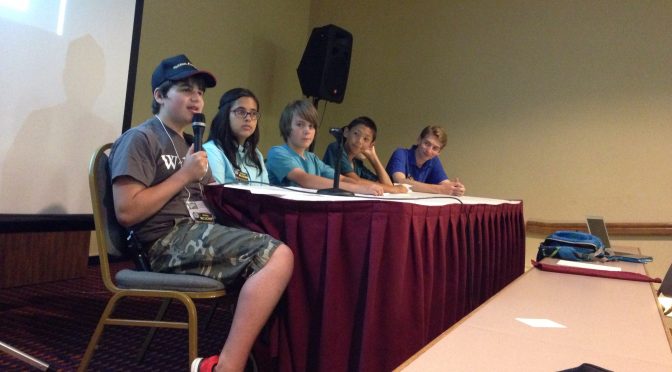
When the Forum began, the audience was faced with a large panel of kids all under 18. Easily 10-12 kids, with a majority of them possessing their General license. Many (if not all) were active members of the Clay Center Amateur Radio Club (and even held positions in the club) which has a whopping 260 members. They boast interesting facts:
- 12 former astronauts have visited the club
- The meeting area for the club also has an astro observatory so kids can star-gaze as well
- Roughly 93 out of 260 members are under 18. (One interesting side note is that if a young person was under 16, then their parents also joined as well due to club guidelines.)
- Many of these kids are also students at a local high school in Brookline, MA: namely Dexter Southfield High School.
One of the club’s mentors is Bob (K5TEC), who has been involved with amateur radio and working with kids for over 20 years; his day job (when he is not a weekend warrior on the radio) is a teacher at the aforementioned high school.
Essentially, after a brief introduction by the students regarding their age, license level, and background, the Q&A ensued. The audience began zinging questions to the youth panel and I’ll share some of the results.
Skip (K1NKR) had begun by asking since many of you are bright, young students, why did you choose to do amateur radio verses, really, anything else? Here were their answers:
- My mom/dad was interested and excited about it, so I became excited too. Additionally, my friends were doing it, and so I wanted to check it out.
- Since my school offered this as a program, I wanted to check it out due to its proximity and my interest in science
- I wanted to meet new people (both other kids in the club and on the air) and learn about astronomy, radios, and cultures other people in the world have
- I have a tech interest and like building computers and working with Linux
- I like playing sports — Fox hunting is fun because I can run around with my friends doing something techy and sporty
- I really enjoy “engineering stations” — having a big project and being “in the thick of it” was fun for me
- I enjoy science (electronics, robotics, rocketry, physics, astronomy, computing) so this seemed natural to get into.
- I liked the idea of contacting folks all over the world and was interested in contesting when I learned about it
So looking over this list, I can see a few trends here:
- A young person became interested because someone else they look up to or respect was already involved in the hobby and remained exceedingly positive and excited about it
- Amateur radio had a natural overlap with many other scientific and engineering disciplines. One facet which I didn’t consider was that for the sportier types — they seemed to gravitate towards the fox hunting
- Giving a kid a “station building science project” that’s all their own to work on, gave them autonomy. For those kids involved in the DIY electronics maker movement, this became another natural extension.
- And probably the most important reason, a bunch of other kids were doing it! — critical mass was achieved — and they did activities together!
After speaking with Bob (K5TEC) he mentioned that most kids went to the club meetings every month — but the club meeting structure would sometimes deviate from having a speaker each week. (Didn’t get an answer about how yet, but getting a reply is in the works) There did exist a core group of kids (4 or more) which kept the ball moving for the rest and were responsible for more of the organization of events etc. In fact, the club also had a weekly youth network run totally by kids. Bob stressed that repeaters are essential to keep kids talking to each other. Bob additionally stressed that is we would need to make sure the club is very social — something to be cognizant of as we move forward.
One question I was particularly interested in, given the hectic schedules of high school students, is when they studied for their exams. The answers were:
- Flashcards / HAM test apps on phone
- At a summer camp sponsored by the club
- Studied after school but primarily most studied during the summer
I think the trend is evident. As a club, we will need to concentrate heavily on licensing kids during the summertime. Moreover, putting into place a summer camp of sorts which focuses not just on the test questions but experimentation etc. will be crucial.
Bob (K5TEC) followed-up with a few more comments.
- He found it VERY important to get kids on the air immediately after they pass their exam. As a result, he would buy a few HT’s, pre-program them, and then sell them to the kids (their parents) at cost, right after the exam.
- He found it took around 9 hours (at a bare minimum) to train the students during the summer
- Summertime is the optimal time to be engaging in licensing kids
- Have an environment where the VE sessions occur that does not scare the kids off and they feel comfortable. (This did not occur to me)
- Numbers and involvement are absolutely essential
So, that about sums up my findings from the forum. I could go on and on, but your coffee is getting cold if you haven’t drunk it all yet, and I need to get back to work. I think one thing is pretty clear, however, and that is to get and retain more young people, we are going to see our club dynamically shift in really exciting and fun ways in the near future. I don’t know about you, but I’m really looking forward to the day (and I hope it’s in the very near future) when I can hear a bunch of young voices in our meeting place giving presentations, talking about their contacts, and maybe even asking old man Smigielski for some help with their radio.
Best and 73,
Brian, AB1ZO