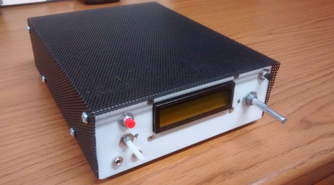
Below is a photo of my BitX-40 kit from Ashhar Farhan VU2ESE in India with my very own custom designed case. The kits are available from http://www.hfsigs.com/
The top cover shown is powder coated steel mesh.

The sheet metal housing was designed in a solid modeling software package called Onshape. This web based software is free to use if your designs are to be available to anyone who signs into an account. This design is “in the cloud” and considered “open hardware”, available to anyone who would like to use it. Below is a screen capture of my Linux desktop running Onshape within a web browser.

With access to a CNC punch press and a 90-ton brake press, a coworker of mine helped out with a bit of “government work”!
I left out some of the detail in the housing to let others enjoy the use of a drill and allow for some creativity with a customized placement of components.

Some of the wires are not needed but may be useful in future “hacks”. The image below shows some of the wires removed from the “Molex” connector. A small sharp object can be used to push in on the barb to remove the contact for a future project.

See http://bitxhacks.blogspot.com/
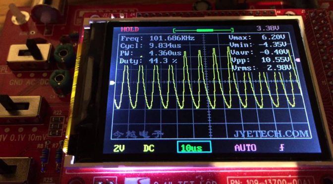
I used my sketch to drive the LCD screen and the SI5351 chip using the Adafruit library. The checkered block moves left and right between the arrows to indicate when I am at or near the end of travel with the tuning potentiometer.

When I move the block all the way to the right with the potentiometer it turns into an arrow and automatically increases the frequency. To make it stop just turn the potentiometer to the left.

I like the ability to scan the band without having to turn a knob!
Below is an image showing 12v and 24v voltage regulators and electrical tape on the housing tabs. 12v is for the majority of the wiring and I used 24v for the IRF510 PA. The black tape looks nice behind the black mesh cover. while testing I measured about 4W RF output with 12v feeding the PA and 16W RF at 24v.

The bottom has extruded “feet” along with stick on feet to keep the rig from sliding.

I used an SO-239 connector for the antenna. I saved the BNC connector from the kit for test gear. The red terminal post is connected to 32v from a repurposed HP printer power supply. The barrel jack is connected to 16v from the same supply.
For more information on the case, you may contact me through my QRZ page.
73,
Mike (AB1YK)
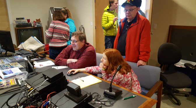
 and Mike (AB1YK) discussing details of Mike's home-brewed transceiver at MakeIt Labs")
 explaining the nuances of digital operation to a young, budding Ham at MakeIt Labs")

 home-brewed BitX20 transceiver at MakeIt Labs")
 DATV station at MakeIt Labs")


 with port (top-middle)")