All posts by Nashua Area Radio Society

Webmaster for the Nashua Area Radio Society

Station Updates At K8EZB

I saw Scott Andersen’s recent plea for articles, including on the topic of station improvements, so I thought I’d respond with a short article on some station updates at K8EZB. Nothing as sophisticated as some here can report, but, for me, meaningful progress. As previously reported, I am back OTA after a 50+ year lapse in amateur radio activity. I have been working mostly on acquiring/restoring equipment for vintage HF SSB stations but decided to first get going with an SDR radio or two, and also get some experience with digital modes. I started with an IC-7300 in late 2017 and after several months of QSOs on SSB, I moved on to FT8. This was a bit of a challenge as it was difficult to find accurate, comprehensive information on radio and software setup. It seemed that everyone offering advice had slightly different ideas on configuring everything. After consulting several online sources as well as Fred and Hamilton, I was able to conduct my first FT8 QSO in late 2018. I was pleasantly surprised at how well FT8 worked, especially considering the highly compromised antenna I am using.

The antenna is a My Antennas EFHW-80-10HP, an end fed half wave (130 ft) wire with a matching network at the feedpoint. This antenna is advertised as resonant on most bands 80m-10m, and I am generally seeing SWR numbers below 3.0 in all cases, and much lower on some bands. These SWR numbers are higher than the manufacturer specifies, but I suspect this is due to certain compromises on my part. The compromises come about due to installation constraints. My location necessitates a bit of stealth, so the antenna is low (15 ft at the highest point), sloping, and folded back into a sort of V shape; it is also below and in close proximity to several steel clad industrial type buildings. Not optimum by any means. However, this antenna has performed far better than expected. Using WSPR and PSK Reporter, it is clear that the propagation pattern strongly favors northeast-southwest. With this antenna, I am consistently able to work stations throughout the U.S. and western Europe on 20m using FT8. And, on a good day, it does even better. One of my early contacts was Rodrigues Island in the Indian Ocean. I have also been heard in Japan on 40m but have not completed a QSO on this band in Japan. The DX is pretty amazing, some due to the antenna, but more likely due to the weak signal capability of FT8.

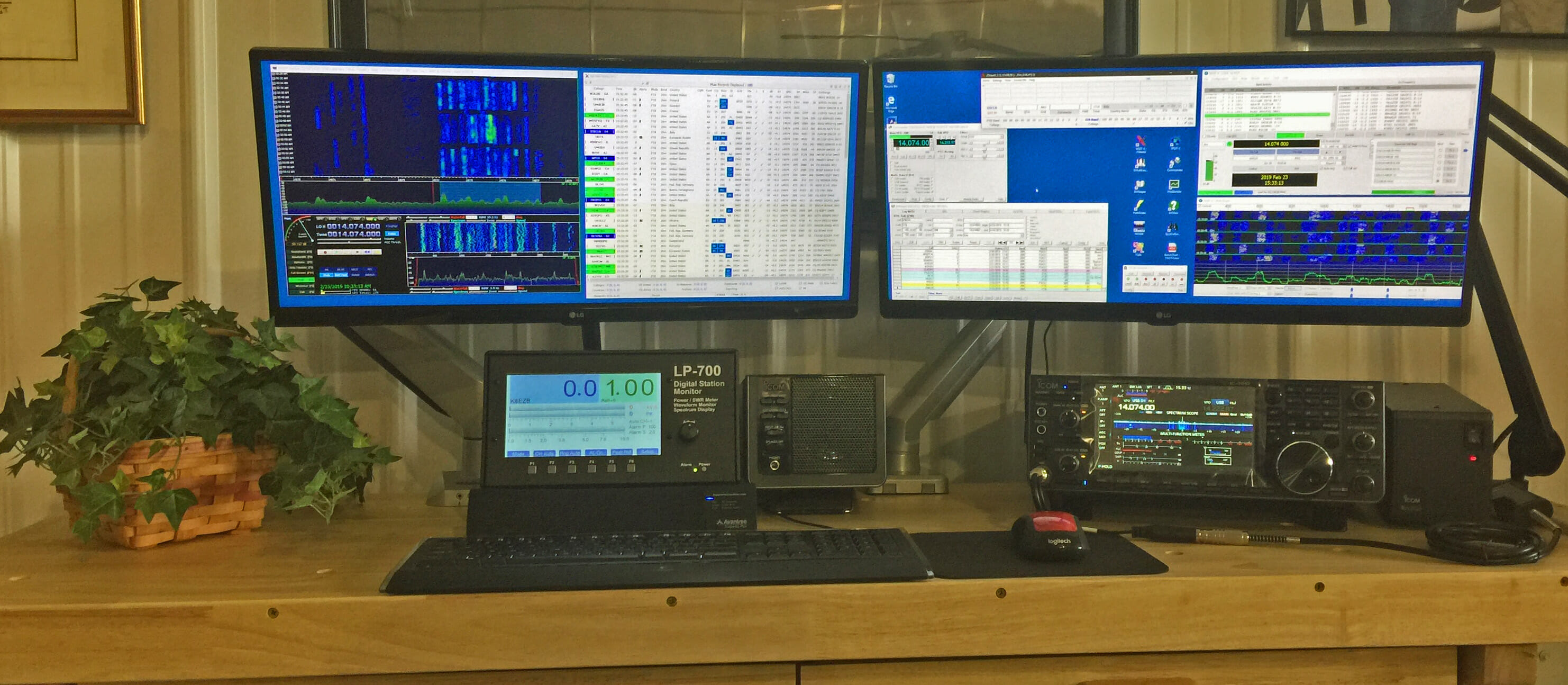
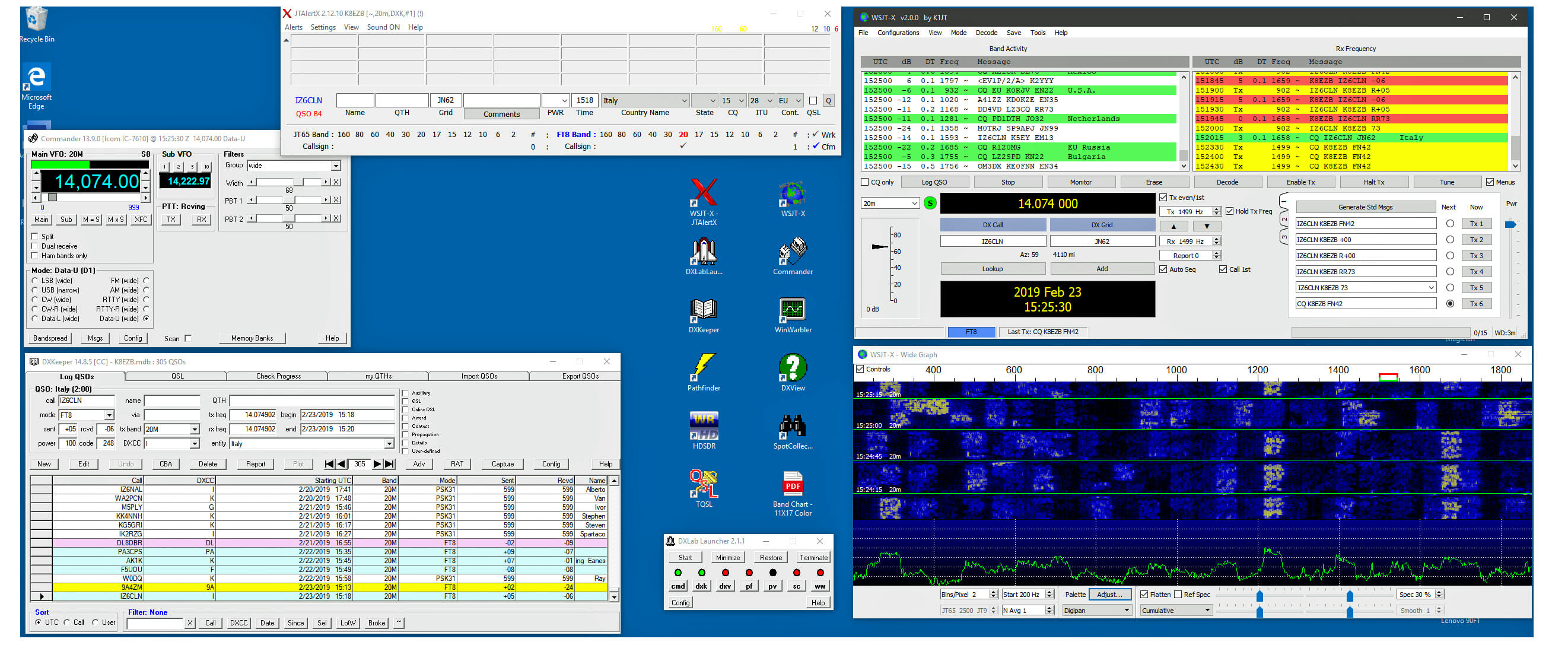
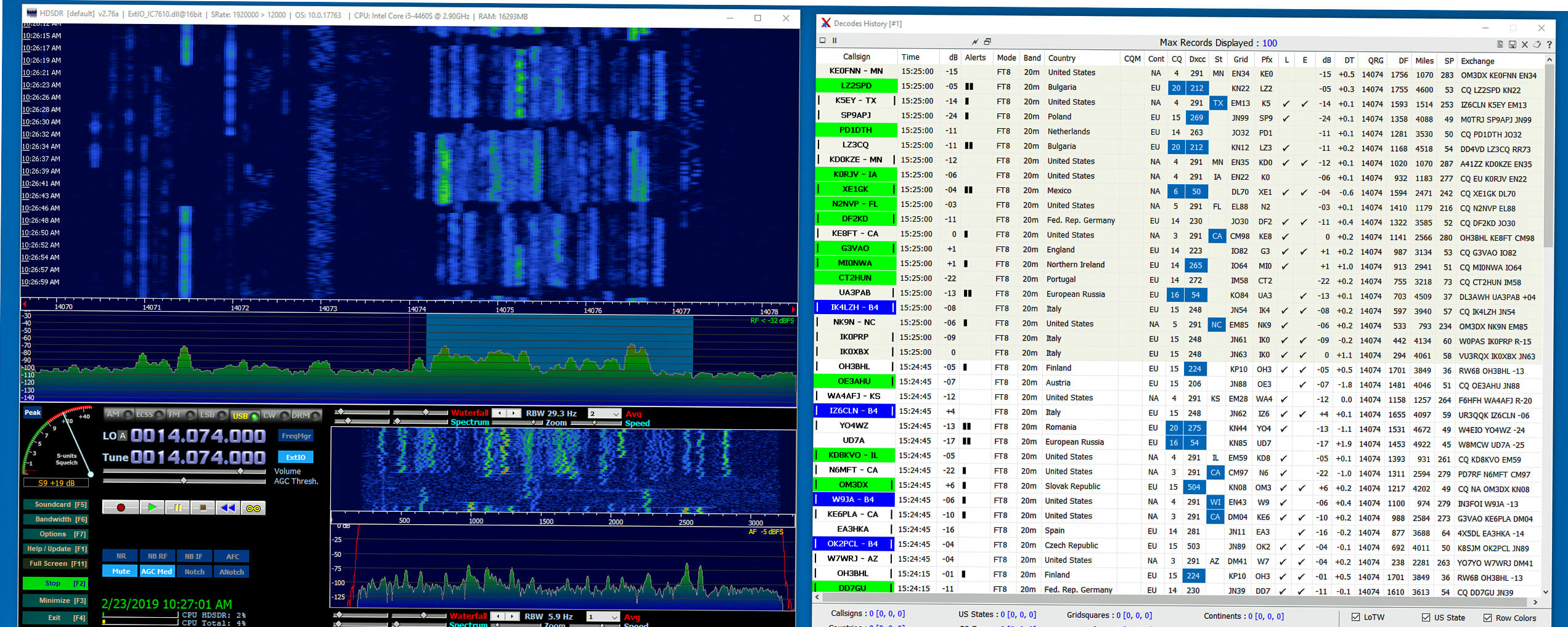
With this early success, I was motivated to upgrade my radio to an IC-7610 in January 2019. This is quite the sophisticated transceiver and I am still learning how to fully utilize its capabilities. Getting the 7610 configured for digital modes was relatively straightforward as much of the setup was very close to the IC-7300. In the process of moving to the 7610, I also added the DX Lab software suite, JTAlert, and HDSDR applications. The DX Lab suite, for me,  is not so much for DX use as for basic logging and support of digital modes. This suite is a software tour de force in terms of capability, but also daunting for a newbie to install and integrate with other apps. There is a very active DX Lab forum at groups.io and the pros there answered my question in short order. Dave, AA6YQ, the developer of DX Lab, has spent a good part of his life developing and supporting this FREE software and is on the groups.io forum daily to answer questions and accept bug reports. I also added HDSDR, an app that is driven from the I/Q output of the 7610 and provides a much expanded and configurable bandscope type capability, well beyond what the native 7610 bandscope can do. (The left window in the Screen 2 photo below shows an example of HDSDR capability).

In the process of adding all this software to my “radio” computer, I decided to upgrade this Core i5 processor by doubling RAM to 16 GB, adding a video card to drive a second hi-res monitor, and replacing the HDD with a SATA type SSD. This went smoothly enough and significantly boosted overall performance. At about this time, the TelePost LP-700 digital station monitor I ordered about a year previous (long waiting list!) finally arrived and I added this to the station. This quite an impressive instrument and I am not yet using anywhere near its full capability.

Once the computer was updated, I branched out a bit to add the Win Warbler module of the DX Lab suite to support RTTY, PSK31 and other digital modes. Both modes worked quite well after getting the setup squared away, and DX in these modes was almost as available as with FT8. My first RTTY and PSK31 contacts were in Europe. In recent days I have installed the latest version of WSJT which supports the new FT4 mode and have made several FT4 contacts. FT4 is said to be optimized for contesting, and while I have minimal interest in contesting, I thought it worthwhile to give it a try. Very easy if one already has FT8 running. JTAlert does not yet fully support FT4 but this is said to be coming soon.

Below are a few photos showing the station and some relevant screenshots.

Next on the station upgrade agenda is the addition of an Acom A1200S solid-state amp and companion 04AT antenna tuner. Also considering adding a Yaesu FTdx-101MP once the reported bugs  have subsided. No such thing as too many radios!

Station Updates
K8EZB


Station Updates
Screen 1


Station Updates
Screen 2

Rick
K8EZB

July Contest Notes

Half Gone

It’s difficult to believe that half of 2019 is already behind us. We’re only a few months away from the start of the 2019-2020 contesting season. As the NARS Field Day totals have shown, there is still plenty of good propagation out there so don’t believe all that talk about the bands being dead. The bands, especially during contests, often have a surprising amount of activity. Take advantage of it.

13 Colonies

The height of Summer brings us things that are an equal amount of fun and competition. Though not a contest, per se, the 13 Colonies Special Event will bring you pile-ups worthy of CQ WW. If you’ve not found some slots to work already, check out the NARS club 13 Colonies effort and get involved.

A Couple of Highlights

I’ll start with one of my favorite contests of July: the RSGB IOTA Islands on the Air contest.

RSGB IOTA Contest [1200Z July 27 to 1200 July 28]

Exchange: RS(T) + Serial No. + IOTA No. (if applicable)

I have often done this contest from the Boston Harbor Islands (NA-148), either Georges Island or camping on Lovells Island. There may be a club field-trip to Georges for a Saturday 6-hour effort. Keep a watch on the Forums section of the website for more information.

CQ WW VHF Contest [1800Z July 20 to 2100Z July 21]

Exchange: 4-character grid square

I’ve done this contest from the top of Mount Wachusett and it is a ton of fun. Of course New Hampshire has a bunch of mountains to try your luck. Walk up the slope and get SOTA points, too!

Take your 6m and 2m all band radio and do SSB, FM, and CW from a mountaintop and rack up the grid squares. This is a really fun way to spend an afternoon.

North American QSO Party, RTTY [1800Z July 20 to 0559Z July 21]

Exchange: Name + state (DC/province/country) for North America. Just name for those outside North America.

The National Contest Journal holds QSO parties and sprints for each mode twice a year. These contests are fun because they are not jam-packed with people. If your new to a mode, or if you just want to sharpen your skills, these are great contests to try.

Until Next Time

Summer is a good time to catch up with family, see a few baseball games [Go Spinners!], or do that outside project you’ve been putting off. But, if you do have some time, get on the air!

73 de

Scott, NE1RD

The RockMite Part 4: The Transmitter

A Quick Review

The RockMite is a very small, but complete, transceiver. We covered most of the radio’s components in the first three parts, but it is worth reviewing. Instead of just rehashing the previous text, we should explore those ideas from a different angle. 

A great place to start any investigation is asking the question, “What problem are we trying to solve?” This is a very relevant question when dissecting a radio. Answering questions like, “What does this particular thing do?” and “Why is this here?” helps us not only understand the results better, but I contend they help us remember the answers better, too.

In part one we explored the receiver. The problem to be solved there was “How do I take energy at radio frequencies and turn them into sounds my ears can hear?” We did that with an oscillator (discussed later) and a mixer, combining two frequencies to produce the four frequencies from two A and B:  A, B, A+B, and A-B. It was the A-B (the free-running oscillator and the received signal) that combined to result in a frequency in the audible range.

In part two we looked at the user interface (UI) of the device, what little of it there is. There were a couple of points there, however, including problems solved like “Can I have an iambic keyer? and “How can we operate this radio on multiple frequencies?” and “How do we turn on the transmitter?” All of these things were controlled by the small Microchip PIC processor.

In part three we looked at the oscillator and saw how the output of the oscillator fed into the mixer for the receiver, and how it also fed forward into the transmitter section of the radio to be discussed today. The magic of the varactor tuning diode gave us a second frequency for the radio that could be directly controlled by the simple microprocessor.

In this last article on the RockMite we will look at the final stages of the transmitter, and specifically the filtering between the transmitter and the antenna.

The Schematic

Below is a schematic for the RockMite that we’ve been using for these articles.

Rockmite Schematic
Schematic for the RockMite transceiver (from QRPMe.com)

The particular part of the schematic we are interested in today is highlighted in the following:

We will discuss each part in turn.

Final Amplifier Stage

The final amplifier Q6 in the RockMite is the versatile and ubiquitous 2N2222A in the nice metal can. We put a heat-sink on the can to keep the transistor cool. The transistor amplifier is fed by a capacitive couple to the first stage amplifier Q5. (Q5 is fed by the oscillator.) 

Q6 is connected to Vdc via an inductor, and to ground when the switching transistor Q3 is turned on. The Q3 transistor is connected to the transmit-receive (T-R) line on the PIC processor and when it powers the gate a connection is made through Q3 to ground, activating Q6. When Q3 is not turned on Q6 is quiet and the receiver can operate.

Filtering

Again, we should begin a discussion with “What problem are we trying to solve?” The final amplifier Q6 is solving the problem of “How do we get our signal amplified to a reasonable level?” Q6 does a nice job with this and the RockMite puts out somewhere around a half-of-a-Watt of power.

But, the trouble with generating signals like this is we also generate unwanted signals as harmonics. So, the question becomes, “How can we pass through the signal we want, but none of the harmonics?”

A good answer to that question is a low-pass filter. Filter design is far beyond the scope of this brief article, but it might be useful to walk through a simple filter design exercise.

I went to rf-tools.com and found a filter design tool. I’ve captured a screen-shot of my work creating a low-pass filter for a 40m radio. That appears below. 

I used some straight-forward parameters for our filter. I want the cutoff frequency to be above 40m so I chose 8 MHz. I left the Passband Ripple (dB) to the value defaulted by the program. And, I left the impedance in-and-out be 50 Ohms. Finally, I told it to choose values that exist in parts catalogs (“standard” values). 

The program generated the schematic near the top, and chose appropriate values for the parts to create the intended filter. The response curve of the filter appears in the graph below the schematic. 

Examine the schematic for the transmitter section, especially the components just before the antenna connection. We have five parts of interest L2, L3, C15, C17, and C19. (Note that C16 and C18 are not populated and are reserved for future versions of the kit.) These five components are the low-pass filter for the radio. The specific parts to be used depend upon the band we want. The values for a 40m band radio are:

L2 and L3: 1 µH

C15, C19: 470 pF

C17: 1000 pF

If you check, these values from the RockMite design are very close to the values selected by our filter design program. (The designers of the RockMite, K1SWL and W1REX, are likely a lot smarter about filter design than I am, so we’ll take it on faith that their value selections are better.) The differences are small: L2 and L4 have 1.0 µH in the RockMite design; the corresponding parts in our designed filter are 1.3 µH. C15 and C19 in the RockMite design match perfectly to the corresponding parts in our filter’s design. And C17 is 1000 pF in the RockMite design, and 820 pF in our filter design. These are all very close. 

The “Insertion Loss and Return Loss” graph for our filter’s design estimates the filter’s performance. The blue line that runs from upper left to the lower right corner shows the loss for a given frequency. Our first harmonic will be at 14 MHz. The line intersects 14 MHz at 27.6 dB, meaning any outputted frequency entering the filter will be diminished by 27.6 dB. Our second harmonic at 21 MHz is reduced by nearly 48 dB.

Why do we care about keeping harmonics down?

The FCC demands it. 

97.307 Emission standards.

(d) For transmitters installed after January 1, 2003, the mean power of any spurious emission from a station transmitter or external RF power amplifier transmitting on a frequency below 30 MHz must be at least 43 dB below the mean power of the fundamental emission. For transmitters installed on or before January 1, 2003, the mean power of any spurious emission from a station transmitter or external RF power amplifier transmitting on a frequency below 30 MHz must not exceed 50 mW and must be at least 40 dB below the mean power of the fundamental emission. For a transmitter of mean power less than 5 W installed on or before January 1, 2003, the attenuation must be at least 30 dB. A transmitter built before April 15, 1977, or first marketed before January 1, 1978, is exempt from this requirement.

So, just guessing, the values in the RockMite’s design for the components probably make the roll-off just a little steeper. Our circuit designed in the on the RF Tools website did a good job, though. If we were really worried about it we could have put another few components in. Check out the following 7th order low-pass filter. At our first harmonic 14 MHz, our harmonics are down over 47 dB. That more than satisfies the FCC.

Wrapping Up

One of the things I love about QRP and low-power operating is I can (almost) understand all the components in the radio. I know what most things do, and I even understand why most things work. I’m still learning. 

This is the last installment of the RockMite teardown. I hope you’ve enjoyed it!

Scott, NE1RD

Radio Amateurs Developing Skills Worldwide