All posts by Ed Deichler

I recently moved to FL after 30 years in NH and a member of NARC during the whole time. To all the newbees in the club, I say welcome to a renaissance in ham radio as the "old stuff" adapts to the 21st century's "connected" world. I was proud to be involved in the club in many capacities over the years, especially Field Day. Everyone will be hearing from me from time to time as the Tiny Elephant lumbers on!

A Stealth Antenna Farm

Living in a community that expressly prohibits ham radio towers often means enduring constant frustration trying to work DX with wire antennas or a multi-band vertical with what is always an inadequate radial field (read: less than 200 radials) over the “worse soil in the world”. My mantra of “work ’em on all bands and all modes” that I pursued for many years from my NH QTH has morphed to “hope I can hear them and they can hear me”. My lot can support a 40-foot tower that would be great for a small beam like the Cycle 24 used during the World Radiosport Team Championship a couple of years ago. Unfortunately, I would never get past a permit for the tower base if I ever tried to put one up.

Ah, but there is hope. The frustrations wrought by CC&R limitations often bring out the ingenuity in hams. Thanks to Layne, AE1N, I visited the website of Jeff, AC0C (see AC0C.com). Jeff lived in a condo with the no-tower restrictions. He looked over the attic where he lived and set about figuring out how to build an array of beams using the roof support structure. In a triangular volume measuring 16 feet at the apex, 20 feet long, and 40 feet wide, he managed to cram in a 22-element array that covers 160 – 6 meters! A scan of Jeff’s website is a testament to a ham’s perseverance to build an antenna farm where common sense says you cannot. Jeff used the popular EZNEC modeling program developed and maintained by Roy, W7EL. The overall configuration of the project shown on Jeff’s website looks like the proverbial rat’s nest. Somewhere on his site he mentions using over 1000 feet of coax, hundreds of ferrite cores, dozens of relays, and numerous switching boards to select the desired antenna while holding the RFI beast at bay.

Intrigued by Jeff’s work, I decided to take a look at my garage attic and see what I could do. My attic measures about 17.5 feet long, 19 feet wide, and 5 feet at the center above the floor. There is usable space beyond the garage over the remainder of the house that runs to the back, providing more depth. Unfortunately, my attic runs N-S so that any fixed antenna would have to be situated to favor a pattern to the E/NE direction for DX. I studied Jeff’s design for his 2-element 40 meter Yagi and decided to scale it for 30 meters. Each element resembles an inverted-V with the lower half of the ends bent at right angles to run horizontally along the floor of the attic. The horizontal portions of each element run toward each other so that the antenna resembles a modified “bent” Moxon antenna. (The Moxon antenna owes its design to Les Moxon, G3XN (SK). It is a 2-element beam that resembles a rectangle, is easy to build, and is forgiving in dimensions for a given band.)

I modeled the antenna with a separation of 19 feet between the elements and inserted loading coils in the driven element to shorten them. The apex height of the antenna is only about 14 feet above the ground so I was not expecting spectacular gain in the primary direction (North). The resulting pattern resembled a low dipole with maximum gain of 4.5 dB North and South, dropping to 3.4 dB at 45 degrees. While this may seem respectable, it occurs for an elevation angle of 45 degrees which means it would not work very well for typical DX angles. Indeed, when I looked at the gain performance at 24 degrees elevation, I had less than a dB. (The astute DX’er will notice that good DX performance occurs for elevation angles of 15 – 20 degrees. When limited to a height of 14 feet, the gain profile at 15 degrees is over 8 dB down from its peak.) Figure 1 shows the layout of the antenna. I realized that I’d be better off with a 30-meter inverted-V dipole off the back of the house.
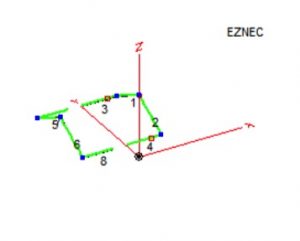
Stealth Antenna– 30-meter 2-element Attic Yagi
Figure 1 – 30-meter 2-element Attic Yagi

Not to be deterred, I then modeled a 17-meter 2-element beam using relays to disconnect the 30-meter element at its coils and inserting an inverted-V element between the 30-meter elements to act as a director for 17. Figure 2 shows the results where the driven element is on the right and the director is at the center.
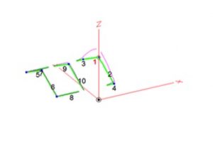
Stealth Antenna – 17-meter & 30-meter Attic Yagis
Figure 2 – 17-meter & 30-meter Attic Yagis

The performance for 17 meters was similar to 30 meters with a modified dipole pattern. The gain was a little better at a 24-degree elevation angle but still less than 2 dB. Again, better to stay with my inverted-V that boasts a 3.8 dB gain toward NE.

While I pondered my next move, it occurred to me that what worked for Jeff might not be the best idea for me. All that coax and those ferrite cores pointed to a lot of blood, sweat, and tears to get rid of RFI gremlins that such close quarters tend to foster. I considered using relays to change bands by lengthening or shortening the antenna elements. However, this would mean control cable wires from the shack to the antennas, themselves inadvertent antennas when transmitting. There has to be a better way.

Then, the long-dormant light bulb in my head came on. Why not try a 2-element wire beam? I looked at a model for such a beam for 17 and 15 meters, 2 elements for each band on the same “boom” and each fed separately. The results showed 17 meters behaves as expected with a gain of 6.2 dBi and a F/B of 21.6 dB. However, the 15-meter portion had a peanut-shaped pattern that was reversed from the intended direction with a F/B of less than 5 dB. I adjusted the height of the 15-meter elements within the available limits but to no avail.

Now what? I looked at the Moxon design again for its space-saving feature to see if I could get more isolation between the beams. I pulled up the file for the 2-element 17-meter beam and another file for a 15-meter Moxon beam. I merged the two antennas and juggled the positions so that the Moxon was a foot above the wire beam. Figure 3 shows the EZNEC model.
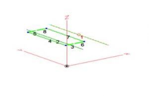
Stealth Antenna – 17-meter Beam with 15-meter Moxon Above
Figure 3 – 17-meter Beam with 15-meter Moxon Above

Figure 4 shows the azimuth gain pattern for the 17-meter beam.
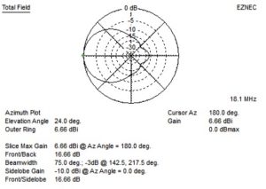
Stealth Antenna – 17-meter Beam Pattern (15-meter Moxon Above it)
Figure 4 – 17-meter Beam Pattern (15-meter Moxon Above it)

Changing antennas for the 15-meter Moxon antenna produces the pattern shown in Figure 5.
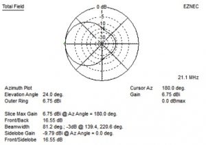
Stealth Antenna – 15-meter Moxon Gain Performance
Figure 5 – 15-meter Moxon Gain Performance

As the model plots suggest, both antennas have nearly identical performance. Success at last! At least on paper minus any interactions and interfering structures such as air conditioning ducts and electrical wiring. Installing two antennas with separate feeds is easy to control with a remote antenna switch. I avoided the need for relays to shorten elements on 17 meters in order to work on 15 meters. I did not want to use relays because of the prospect of RFI causing them to trip, and the need for extra wires from my shack plus ferrite cores for RFI suppression. Now on to the fun part – BUILD IT.

Ham Radio and CC&Rs: Back to the Future

As many of you may know, I QSY’d to Florida last summer and now live in a large retirement community.  With the move I find myself in an area tailored for the elderly – single-story homes with wide doorways; age minimum of 55 years old; small lots with few trees; landscape and lawn-care services; and the omnipresent golf carts.  The biggest industry besides the care and feeding of golf clubs is health care.  While I do not consider myself elderly at least for another 10 years or so, it is nice to know what lies ahead.

The Villages, FL is probably the largest planned retirement city in the country.  The city’s goal is to make retirement as enjoyable and comfortable as possible for residents, free from those annoying things you had to put up with during your working career up north.  That “freedom” factor is often embodied in fine print on one’s deed that is called Covenants, Conditions, and Restrictions (CC&Rs).  Hams are familiar with the term since those who live in apartments or condominiums have to contend with “no outside physical structures for non-commercial antennas, or related paraphernalia attached thereto to one’s domicile”, or similar gobbledygook that means no towers and antennas.

So why in the world does a guy who had two towers, stacked beams, contested regularly on 160 – 10 meters running the legal limit in power, and has worked them all (DXCC and states) pull up stakes for such a place?  I’m still asking myself that question, although I must admit being able to cycle, run and swim in January and February is pretty cool.  I’m still in good shape for tower climbing if I find a big station off the reservation that needs some help.

But take heart.  Life’s changes mean new challenges and ham radio is no different.  Thanks to technology and ham radio ingenuity, there are ways to coexist with Big Brother and still enjoy the hobby.  Before I made the commitment to make the move, I checked out the local radio club’s site at K4VRC.COM that contains some useful and clever stealth antenna configurations one can implement.  A number of local hams have an “ugly” flagpole made of PVC pipe that encases a vertical antenna.  The base hardware is disguised with a fake rock or a nice flower bed while the lush lawns hide a radial field.  It didn’t take me long to settle on a Hustler 6BTV vertical for my flagpole antenna.  The 6BTV is attractive because it requires no top hat capacitive loading that would not work inside PVC pipe.  It is about 24 feet in height which fits in with the CC&R limit of 22 feet for flagpoles.  (The two feet that stick out are part of the 80-meter coil and are hard to see.)

I’ve been operating about four months now with the vertical and have had some success with it.  I managed to work 500 stations during the ARRL CW DX contest in February and several hundred more during a couple of the RTTY DX contests.  I find my hamming has a familiarity that hearkens back to when I got started.  As a newly minted General in the 1960s I was confined to low wire dipoles; the Heathkit DX-20/DX-40/DX-60 line of transmitters; and a Hammarlund HQ-100 receiver.  I was happy working the states and especially the counties, the latter being “retired” at ~3035 confirmed.

OK, what now?  Why, more antennas, of course.  The back of my house has a peak about 20 feet up that I figured would be a good spot for a pole bolted in place to support a dipole.  I have a tree on the front corner of my property that is 30+ feet tall, fine for one end of a multi-band dipole.  Back in the early 80s when the WARC bands were new, I built a tri-band dipole for 30, 17, and 12 meters.  This simple antenna worked well since there were few beams and even fewer amplifiers on these bands so everyone was on an equal footing.  I decided to go with a 40/17/12 meter combination to give me another option for 40 meters.  I hung the antenna between the tree and pole on the back of the house, the 40-meter dipole resting just a foot or two above the roof.  The 17 and 12-meter antennas were made with insulated wire and run across the roof to tie-off points on the side of the house in a tilted inverted Vee configuration.  Other hams in The Villages have run similar antennas across their roofs and found them to work OK with a tuner.  (Such antennas are also hard to see even for the neighborhood vigilante.)

The new antenna allowed me to cover the entire 40-meter band without a tuner.  The 12 and 17-meter antennas, however, did not perform as well as I had hoped.  Propagation was a factor but I also noticed that the wires worked their way under the roof shingles and I did not want them pulled up when the antenna flexed on windy days.  Time to figure out a new scheme, especially when the XYL complained about the dipole being visible from the street.

I studied the pole on the back of my house where the dipole was secured and had an idea.  Why not mount the center insulator on the pole and feed the antenna ends to the ground as a series of inverted Vee antennas?  This approach was desirable for two reasons: (1) it was hidden from the street view; and (2) I could orient the inverted Vees to the Northeast to favor Europe.  I found that I could secure the ends of the 12-meter antenna off the ends of the soffit at the back peak of the house.  The 17-meter inverted Vee hangs off one end over a lower roof and is tied off to a bush on the corner of the Lanai, and the other end is tied off to a hook on the other side of the roof.  The 40-meter antenna runs from a small tree at the back of the property on one side and to a stake that supports a rope to my flagpole on the other side.  The coax is taped along the pole and runs across the roof to a row of hooks along the soffit to the front of the house and into the shack.  A check of the view from the street shows only the pole to be visible.  As for the ends of the antennas, well, I love black Dacron rope.

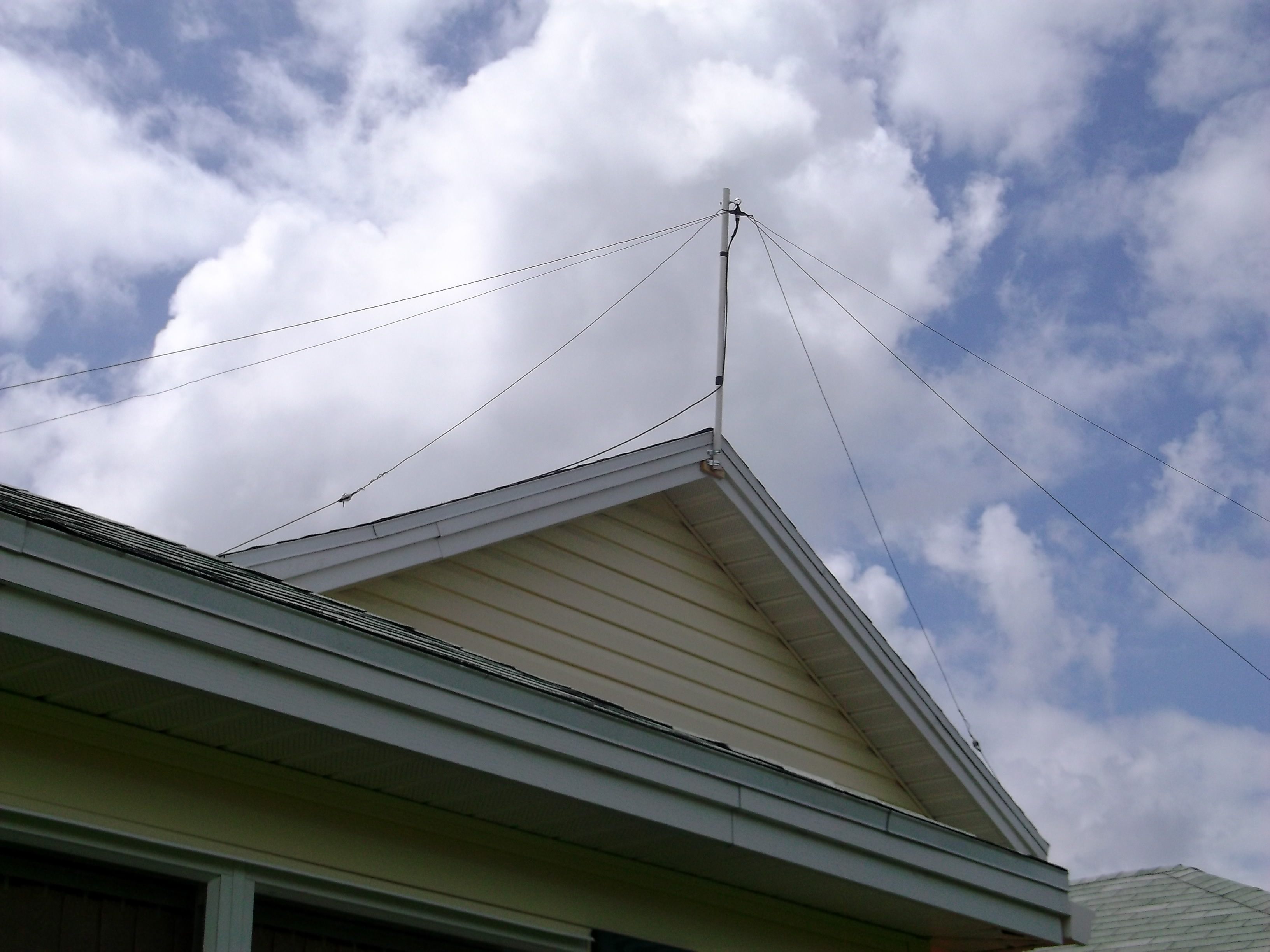
The figure below shows the antenna from its pole mount.  The center feed point is visible at the top of the pole.  The top dipole is the 40-meter antenna, followed by the 17-meter antenna and finally the 12-meter that is tied off at the peak roof line.  The 40-meter antenna is forward-most, meaning it is the most Northeasterly of the three.

CC&Rs - Triband antenna installed at K2TE
Triband antenna installed at K2TE

The tri-band inverted Vee antenna is a very simple design and it works.  Some pruning may be necessary to tune the antennas due to interaction with each other or nearby objects.  I’ve been able to work stations on 17 meters as propagation allows, but nothing much on 12 meters for the same reason.  (Zack, W1VT has designed a WARC tri-band dipole that uses ladder line for matching to a conventional wire dipole strung between trees.  Unfortunately, I do not have the trees to try this.)

So here I am with a capability to operate 80 – 10 meters again.  I’m limited to 100 watts for the time being.  Adding my AL-1200 beast in line is not an option since my 6BTV is about six feet from the rig.  Besides, 1.5 KW into the antenna will be like unleashing an EMP on the neighbors as well as myself.  When I sit back and ponder my setup, I find myself back to the future with simple antennas like I started out with.  Ahh, but this is the 21st century and technology comes to the rescue.

Stay tuned.

73 de TE

New England QSO Party

New England QSO Party

For a number of years, Tom, K1KI has been managing the New England QSO Party (NEQP) that takes place the first weekend of May, usually right after NEARfest. This year’s event will be held May 7 & 8. The NEQP has become very popular among county hunters since many of the Yankee Clipper Contest Club members get on the air from New England with several of them going mobile. The small size of the NE states and counties make it ideal to spend a few hours in the car running pile-ups from county lines.

If you’re new to the hobby, this is an excellent time to experience the thrill of being a sought-after station. Stateside QSO parties are a great stepping stone to larger operating events like Field Day. Whether you go mobile or not, there are plenty of stations looking to work NE.

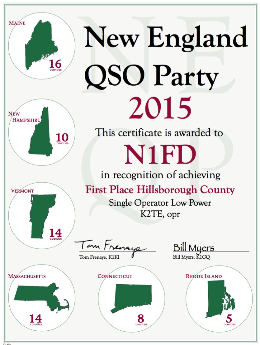
2015 New England QSO Party Certificate
2015 NEQP Certificate

Lest you think you need to slog it out for hours to get anywhere, I won the NH Hillsborough Low Power category, using N1FD, for 2015 with only 162 QSOs. Tom spreads the wealth to maximize enjoyment.

If you’re interested in giving it a try, check out NEQP.ORG for details. In past events, NARC has used an interactive spreadsheet for those who would like to operate with the N1FD callsign so that folks can select a time and frequency for operating.

Finally, as a warm-up, look for me from Marion county, FL the weekend of April 30 – May 1.

73 de K2TE

Radio Amateurs Developing Skills Worldwide