All posts by Ed Deichler

I recently moved to FL after 30 years in NH and a member of NARC during the whole time. To all the newbees in the club, I say welcome to a renaissance in ham radio as the "old stuff" adapts to the 21st century's "connected" world. I was proud to be involved in the club in many capacities over the years, especially Field Day. Everyone will be hearing from me from time to time as the Tiny Elephant lumbers on!

Little Pistol DXing

For many years, I enjoyed chasing DX from my NH station with two towers, multiple beams, an 80-meter 2-element quad and a 160-meter Inverted L.  I got spoiled with the AL-1200 hammer I used almost constantly whenever a DXpedition came on the air to bag it quickly.  The setup allowed me to bust a contest pileup in just two or three calls.  Ah, the good ol’ days.

I’ve been in FL now for 18 months in a covenant-restricted retirement community.  I was fortunate to find a place with a fair amount of open property that allowed me to put up a couple of low inverted Vees and a multi-band vertical.  The wire antennas drape off a pole on the back of the house, out of sight of most of my neighbors.  The vertical is enclosed in a PVC flagpole with just the 80-meter “stinger” poking out the top.  It may be an ugly flagpole but it falls within the covenant permissible guidelines and, more importantly, keeps the village aesthetic vigilantes off my back. I have about 32 radials fed from the base of the vertical in a ¾ pie-shaped field with lengths varying from 55 feet to 10 feet.  While this is far from the standard practice of at least 100 radials of 65 feet or more (assuming 80-meter capability), it is better than nothing.

As one might expect, DXing has been a far cry from what I was used to.  Hearing stations is a chore, even with a K3 over my old FT-1000MP.  I often find myself irritated at the juicy spot reports from New England that I cannot hear.  Part of the problem is geography; I am at a lower latitude and I line near Ohio longitudinally so gray-line effects are different.  One might think the high threat of thunderstorms down here also generates a lot of noise but it has been dry and quiet during the fall and winter months when DX is most active.

So what is an old DXer supposed to do?  Answer: Back to the future.  When I got my Novice license back in high school, I put up an end-fed long-wire antenna for 80 meters and a dipole for 40 meters, both of them much lower than 1/4-wavelength above ground.  The long-wire was fed with 300-ohm line.  Why?  Because that is what my Elmer and high school buddy told me to do.  I was clueless about matching, common-mode currents and RF in the shack.  I had a Hallicrafters S-38 reconditioned tube receiver that had a barn door-wide filter for CW.  You can understand why it was a thrill to work states west of the Mississippi.  If nothing else, I learned to appreciate a QSO and to be patient when trying to work someone.

My present station has the advantage of all the technological improvements in signal processing and automation that have mushroomed since the tube days.  Stations are still weak when I do hear them but I can work them if they aren’t too busy.  Contesting is actually better since many stations crank up the amplifier and plead for stations late in the contest.  Using an amplifier here is problematic.  My vertical is about eight feet from the shack so RF saturation would be likely.  Furthermore, I would need to run a 220 VAC line to the shack to avoid brownout when using 110 VAC with an amplifier.  The worse thing, however, would be EMP effects on the neighborhood breaker systems.  It seems building contractors have switched to breakers with a much lower RF tolerance than before.

So what a desperate DXer supposed to do?  The easiest thing I can do is put down more radials.  As I mentioned, my radial field is far from ideal, even if I had moist, loamy soil instead of sand.  An ideal radial field would be a copper sheet surrounding the vertical.  In the climate here, it would turn green in a few weeks so it would look like a California painted lawn if it isn’t stolen first.  I decided to double the radial field I have to provide more return paths for the RF currents.  I have not modeled my antenna to see what kind of radiation pattern I have but it is a good bet that the so-called takeoff angle for bouncing off the ionosphere is 40 degrees or higher.  Conventional theory says that a takeoff angle should be 15 to 20 degrees, values usually achievable with yagis mounted 1/4-wavelengths or higher.  The hope is that I can pull-down my takeoff angle enough to where I fall into the usual DX footprints.

When I installed my original set of radials, it was a time-consuming effort to work each wire down through the thick St. Augustine grass here.  I finally got smart one day when trimming the walkways with my weed-whacker set up vertically.  I found that I can lay out the wire and walk along it with the weed-whacker cutting a narrow slice through the grass.  I then drop the wire down into the cut, add a few staples and close the grass around the cut.  The cut will be completely grown over in about a month.  (This technique will work in New England if you have a manicured lawn; the rocks in a natural lawn tend to mess things up.)  To date, I have added eight radials so it is still a work in progress.

For those of you with a modest station, take heart.  With today’s transceivers, propagation predictions, and worldwide spotting it is possible to achieve DXCC on several bands in less than a year.  I have been fortunate to work them all when I was a “big gun”.  As a “little pistol”, I’ve managed to work 176 countries with 144 confirmed.

The chase continues…

Ed (K2TE)

Moxons in the Attic (Part 3)

Well, another month has gone by on my two-band attic Moxon antenna project.  If you recall from last month, I was left with a perplexing matching problem with the 15M antenna while the 17M one works fine.  I had to figure out how to come up with a way to chase down what was causing the problem.  I guess this just proves that there is no such thing as a simple, straightforward antenna project.

So, with a can of suds as brain fuel, I sat down to methodically list what to do and rule out possible causes.  As a starting point, I connected a 1:1 balun to the 15M and a no-balun, connection to the 17M beam.  This time, I decided to do all measurements from the shack so that losses from the shack coax would be taken into account.  SWR checks on each antenna were consistent with earlier measurements, namely an SWR <2:1 on 17 and 15 meters using the 17M Moxon while rising to 4.4:1 – 6.0:1 across the band when switched to the 15M beam.

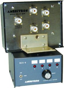
Ameritron RCS-4 Antenna Switch
Ameritron RCS-4 Remote Antenna Switch

The next step was to rule out any leakage inside the RCS-4 remote switch.  I decided to try this step because I was suspicious of the current design of the RCS-4.  I had used one for about 20 years in good ol’ NH weather without a problem.  The new unit, however, felt light.  The relays in the remote unit were too quiet for my liking, and an AC power pack replaced the internal power supply from the old unit.  I moved the 17M connection to the last position on the switch so that it was on a separate relay from the 15M antenna and measured.  No change.  I then disconnected the 15M antenna from the switch, leaving it open, and measured.  Again, no change.  I connected a jumper across the 15M connector to short the antenna elements together and measured both bands on the 17M antenna.  As observed earlier, the 17M beam works fine on both bands, indicating the 17M Moxon does not see the 15M one.

OK, so now what?  It was clear the 15M beam was being influenced by the 17M one.  I decided to check the phasing between the two beams wherein the center and shield sides of the coax were connected to the respective sides of each beam.  The casual observer will recall a demonstration by Dale, AF1T of what happens when stacked beams are fed in-phase or out-of-phase.  However, since I’m operating on two different bands, why do I want to do this?  The answer: electromagnetic behavior is complicated; just ask J. C. Maxwell.

To do this, I connected a center insulator that has an integrated PL-259 connector to the 15M beam.  I had used this connector in the past and it was already marked for the shield and center conductor sides.  I checked the balun connections that I had removed from the 15M beam, found the shield side on the first try, and marked it.  I installed the balun on the 17M beam which now represented the opposite of the previous antenna connections.  My rationale for doing this was that a direct, non-balun connection showed a good match on 17M.

Measurements from the shack on the 15M beam now showed an average SWR of ~3.3:1 across the band, better than before but not great.  Measurements on the 17M beam when tuned to 15M, however, were clearly worse with an average SWR of 4:1.  Measurements on 17M were also degraded with the SWR above 2:1.  Clearly, the antennas were not happy with this arrangement.  I decided to disconnect the 15M beam from the RCS-4 switch based on the noticeable change observed on the 17M beam, and remembering that the 17M beam did work before on 15 meters.  When I tuned the 17M beam across 15 meters, the SWR jumped to 8:1.  I was now suspicious of what effect the balun was having on antenna behavior.  Why should the performance be significantly worse with a balun when compared to the simple split feed of the center insulator?

I pulled the insulator and the balun off the antennas to check the connections again.  I was surprised to find that the center insulator showed an open-circuit for the center conductor side.  Even more surprising was the fact that the balun showed the same thing, meaning NO CONNECTION to one side of each antenna.  I looked at the lugs for each device where the center conductor was and noticed that they were loose.  Furthermore, the PVC plastic around each lug had been melted from my efforts to remove old wire and solder from the lugs.  Murphy, you struck again!

In desperation, I took a hacksaw to the top of the center insulator connector to check the center wire inside.  I found it to be intact so I then removed the eye-bolt and replaced the lug with a new one.  The connection to the PL-259 center conductor now worked.  I could re-use the “topless” insulator since it would be in the attic and not exposed to rain.  I scrutinized the same lug on the balun and figured the melted PVC plastic, as in the case of the center insulator, must have formed an insulation between the lug and the eye-bolt to the balun center conductor.  I scrounged around the junk box and found another PL-259-equipped center insulator I could use.

I trudged back up to the attic and reinstalled the center insulators on each beam and scrambled back to the shack to measure things.  This time, SWR for the 17M Moxon was flat across the 17M band vice over 2:1 before.  Performance on 15 meters for the 17M beam was now down to 2.2:1 which was certainly better than 8:1.  The 15M Moxon, however, still showed slightly greater than 3:1, indicating some interaction was still going on, or still a mismatch.  Now what?

As I pondered what could be happening, I remembered something about RF chokes around the coax jacket to prevent common-mode interference.  I recalled my education about rejecting common-mode interference from a presentation by Chuck, W1HIS, aka, Doctor “Ferrite”.  Chuck is the de facto High Priest of Common-Mode Exorcism to prevent RF from entering the shack via feed lines and anything else that comes into the shack.  (By day, Chuck is an MIT professor emeritus.  The Dr. Ferrite title has been bestowed upon him for his prolific use of ferrite chokes throughout his house.  He hates RF noise.)

Admonishing my transgression, I grabbed a couple of ferrite cores from my junk box and scurried up to the attic.  I wrapped as many turns as possible of the RG-8X coax line from the shack until there was no more slack on the attic floor.  I also wrapped a few turns of the coax from the 15M Moxon around a core.  Sadly, there was no change when I checked each beam from the shack.  Well, at least I was relieved that I did not appear to have RF sneaking back into the shack and playing tricks on me.

OK, what next?  As I pondered what to do it occurred to me that the antennas were fed in-phase wherein the shield side of each antenna was the same.  The logical next step was to feed them out-of-phase.  I removed the center insulator for the 17M Moxon and reversed the leads so that the coax center conductor was now under the shield side of the 15M Moxon.  A sweep of the 17 and 15-meter bands while feeding the 17M Moxon showed an SWR under 2:1 for each band.  Switching to the 15M Moxon and sweeping the band still showed the perplexing behavior of SWR greater than 3:1.  I did a sweep of several MHz above and below the 15-meter band to determine if the 15M Moxon might be resonant elsewhere but it was not.

Well, at this point it looks like I can operate two bands with the 17M Moxon so it is not a total loss.  I am back to where I started in terms of performance of the antennas except the flaky balun is gone for 15 meters.  I checked how the EZNEC pattern looks when operating at 21 MHz with the 17M antenna and it does not look much different from 18 MHz.  On the bright side, I can always use the tuner in the K3 to make the 15M Moxon play right for the band, giving me some flexibility if I can hear a station better on one antenna than the other.  Like I said, the electromagnetic behavior is a complicated phenomenon.

Ed, K2TE

Moxons in the Attic (Part 2)

 It has been a couple of months since I wrote about my project to build a Moxon antenna for 15 and 17 meters in the attic of my garage.  The weather has since cooled down to where I can work in the attic without sweat dripping in my eyes and my hands slipping on everything.  When I wrote about my initial measurements in the last article, I was experiencing erratic SWR readings on the 15-meter beam with the lowest SWR being around 23 MHz.  I did some recomputing and figured I would need to lengthen each element by 24 inches to bring resonance down to 21.1 MHz.  I was not too thrilled with the idea of having to solder wires in the cramped space of the attic so I decided to check the SWR behavior again.

There is an old adage in carpentry that says measure twice, cut once.  The same applies for adjusting antenna elements except “twice” becomes “until consistent”.  When I connected my analyzer to the 15-meter beam, I did the flex test of the connecting cable.  Lo and behold, the SWR started jumping around.  I checked the connector hardware and noticed the PL-259 reducer shell was loose.  Once I tightened it, I found the resonant point to be way down at 19.0 MHz.  My antenna was too long; it would have to be SHORTENED by 24 inches.

Armed with the new readings, I shortened each element accordingly and measured the antenna again.  My efforts paid off with a reading of 1.1:1 at 21.2 MHz and a 2:1 bandwidth from 20.8 to 22.78 MHz.  I was now ready to move on to final installation.

I needed more coax, a couple of baluns, and a remote antenna switch to complete the project.  A hamfest scheduled for the first weekend in October in Melbourne, FL looked like a good prospect for finding what I needed.  Unfortunately, Hurricane Matthew had other plans and forced a postponement of two weeks.  When I attended the hamfest, many vendors were absent due to conflicting plans so pickings were slim.  I did manage to find the baluns and more coax but the switch would have to be ordered.

I found an Ameritron RCS-4 online at a reasonable price and ordered it.  I had used this model for many years when in NH so I was familiar with its reliability.  When the switch arrived, I hooked it up to check it out before installing it.  Murphy said hello to me with a non-functioning control unit.  I called the company I bought it from and they arranged to have it returned for a replacement.  I finally received a working unit two days before Thanksgiving.  With the CQ WW CW contest coming up, it came just in time.

I routed a 50-foot run of coax from my shack around the front of the house and into the garage attic.  Figure 1 shows the coax run.  If you can’t see it, good; I do not want the Village Vigilantes to come knocking on the door to question the aesthetics of the cable.  Figure 2 shows a closer view of the coax entering my attic.  So far, the XYL hasn’t noticed it so I’m safe.

Stealth Antenna - Coax Run Across Front of House
Figure 1. Coax Run Across Front of House
Stealth Antenna - Coax into the Attic (Upper Left)
Figure 2. Coax into the Attic (Upper Left)

The next step involved hooking up the baluns and the remote switch which was a straightforward process.  Once everything was in place, I fired up the rig on 17 meters and found a spot for UA0ZC.  I was happy to hear him and gave Val a call.  A minute later I had a rare one in the log without having to hammer away indefinitely.  I checked 15 meters and did not find much activity.  The operational SWR was a bit higher than my measurements but still under 2:1.

At least, it started out that way.  I got on the air the next day and found the SWR on 15 meters hitting 6:1 and higher.  I made a trip up to the attic to find out what was going on.  At first glance, nothing appeared amiss.  I plugged the analyzer into the 15-meter beam and noticed the SWR jumping around.  Flexing the cable made some difference but not much.  My initial thought had been some incomplete switching in the switch unit but the SWR behavior when directly connected to the analyzer ruled that out.  I tried swapping baluns between the two beams to no avail.  With other pressing holiday matters to attend to, I decided to remove a balun from the 17-meter beam in favor of the 15-meter beam.  (During my troubleshooting efforts, I noticed the 17-meter beam behaved as designed, with or without a balun.)  The 15-meter beam shows no discernible difference in performance with or without the balun.  Figure 3 shows the present feed point installation with the switch on the attic floor.

Figure 3. Feed Points and Switch

I have to admit that I am stumped at this point.  There is some consolation, however, in that my K3 tuner easily matches up the 6:1 SWR imbalance.  I imagine there is interaction with the other structures in the attic (house wiring, AC ducts, 17-meter beams, etc.) that are making a good match difficult to achieve.  At any rate, I am happy to have a worthwhile antenna for 17 meters vice my low inverted V.  As the sunspots continue to degrade, 17 meters may well end up as the MUF.

Ed, K2TE


Radio Amateurs Developing Skills Worldwide