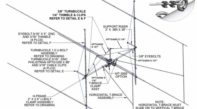
The final major component in our 2m EME Station Upgrade to be assembled is the 2MXP28-32-2X2-3K H-Frame which will support our four 2MXP28 Antennas. The H-Frame is one of the most mechanically complex components in our EME antenna system…
We are almost ready to put our new 2m EME Antenna System. We’ve been working to pre-assemble and test all of the components in the new Antenna Array. The last major component to be prepared in the H-Frame assembly which is used to mount our four new antennas on our Tower. The H-frame component is one of the most mechanically complex parts of our Antenna System. The link above shares all the details of this part of our project.
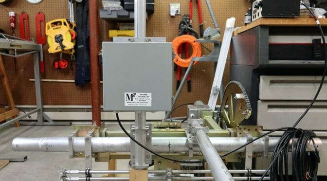
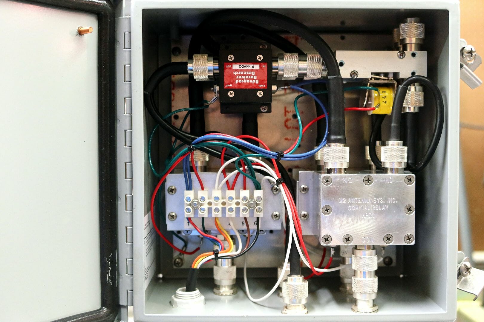
The next major component in our new EME station is the assembly of the Elevation Rotator. This step also involves pre-assembly and testing of the MAP65 Pre-amp Housing, Antenna Power Dividers, Tran…
We are continuing to make progress on our 2m EME Station build. The latest step in the project was to assemble and test the Elevation Rotator and the MAP65 Preamp System. The article at the link above explains what we did to complete this step in our project and to test what is a major sub-system in our 2m EME Station.
MAP65 Preamp Housing
This part of the project includes installation and testing of the MAP65 EME Preamp Housing on the rotator assembly. This unit and the rotator are tested along with a Green Heron Engineering RT-21 Rotator Controller and a MAP65 EME Sequencer.
We are getting close to installing our new 2m EME Array on the tower. The final preparation step in our project will be the final assembly and preparation of a large H-frame that will mount the four antennas in our EME Antenna Array.
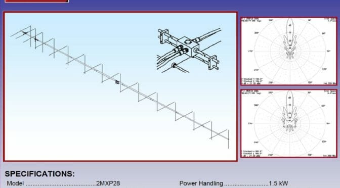
The next step in our EME project is to assemble the four M2 Antenna Systems 2MXP28 Yagis. The four EME Antennas in our array will have a total of 112 elements! These antennas are large, cross-polarized yagis. They feature 28 elements each on 34 1/2 foot booms…
We are building four M2 2MXP28 Antennas to be mounted on an M2 Antennas 2X2 H-Frame. It is important that the four antennas be identical so they operate properly as an array. This includes things like symmetrical mounting and alignment of each antenna’s vertical and horizontal elements and the associated feed points.
The article in the link above covers the steps, tips, and tricks that we are using to assemble four of these large, 2m X-pol Yagi Antennas. The approach, tools, and techniques are applicable to a wide range of VHF and UHF Yagi antennas.
We use cookies to ensure that we give you the best experience on our website. If you continue to use this site we will assume that you are happy with it.