
Previously, a 4-channel audio multiplexer [1] was described for use in a QRP SSB transceiver. This paper describes the multifunction, analog audio processor printed circuit board upon which the 4-channel multiplexer resides. We provide a recap of the functions provided by this circuit card in the sections that follow.
Circuits Included on the Audio Processor Circuit Board
All of these circuits have been delineated on the circuit board layout:
a +9 VDC fixed voltage regulator [2],
a +3.3 VDC adjustable voltage regulator [3],
a +3.0 VDC adjustable voltage regulator [4],
a 4-channel MUX decoder [5],
a 4-channel bidirectional audio MUX [6],
a receive Class AB audio leveler preamplifier [7],
a receive audio leveler/attenuator [8],
a receive Class AB discrete audio amplifier [9],
a receive audio-derived S-meter circuit [10],
a receive IF AGC-derived S-meter circuit [11],
a transmit microphone preamplifier [12], and
a transmit microphone SSM2167 audio compressor [13].
Circuit Descriptions
+9 VDC Fixed Voltage Regulator
An LM317 adjustable regulator is used in fixed voltage mode. This voltage regulator provides filtering on the adjust terminal resulting in much quieter regulation than that of a 7809 fixed voltage regulator. It provides +9 VDC for the +3.0 VDC and +3.3 VDC voltage regulators, as well as the Class AB audio leveler preamplifier.
+3.3 VDC Adjustable Voltage Regulator
An LM317 adjustable regulator is used in fixed voltage regulator mode. A trimpot is provided to adjust the output voltage to +3.3 VDC. This regulator is used to bias the Analog Devices SSM2167 Low Voltage Microphone Preamplifier with Variable Compression and Noise Gating.
+3.0 VDC Adjustable Voltage Regulator
An LM317 adjustable regulator is used in fixed voltage regulator mode. A trimpot is provided to adjust the output voltage to +3.0 VDC. This regulator is used to bias an electret microphone. The electret microphone requires +3.0 VDC bias with a source impedance of 2.1 kohms.
4-Channel MUX Decoder
The 4-Channel MUX Decoder is used to generate 4 x 8-bit states, each of which selects a unique MUX channel. The circuit consists of one 2-channel relay and four CD4072 2 x 4-input CMOS OR gates. The 2-channel relay is used to decode +12 VDC to one of four MUX decoders at a time. The MUX decoder provides +12 VDC to series and shunt MUX switches, one mode at a time. There are two transmit and two receive modes, as will be described in the sections that follow.
4-Channel Bidirectional Audio MUX
The audio mux is used, bidirectionally, to route audio to the balanced modulator during transmit functions and from the product detector during receive functions. A single mixer serves as both a balanced modulator and a product detector for the transceiver.
The audio mux is implemented with switches consisting of series and a shunt 2N7000 enhancement mode MOSFETs in each of the four channels. The series and shunt elements provide additional switch isolation.
Receive Class AB Audio Leveler Preamplifier
A discrete Class AB audio amplifier is used to drive the W2AEW audio leveler input at a typical listening volume. This signal will vary as the audio source material. The output of the preamplifier will produce up to 100 mW of clean audio power, which is enough to drive the leveling circuit.
Receive Audio Leveler/Attenuator
An audio leveler/attenuator has been described on Alan Wolke’s, W2AEW’s, YouTube channel. This leveling circuit accepts audio at a typical listening volume to produce up to 50 mV output. This leveled output must be amplified further so that it can drive a loudspeaker, or a set of headphones.
Receive Class AB Discrete Audio Amplifier
A discrete Class AB audio amplifier is used in receive mode to either amplify the product detector output channel of the MUX directly, or to amplify the output of the audio leveler/attenuator to loudspeaker listening volume.
Receive Audio-Derived S-Meter Circuit
An audio-derived S-meter circuit is used to drive an analog input of the Arduino MEGA 2560, Rev. 3, so that an S-meter reading may be displayed on a 3.2” TFT display. The output of the shunt feedback preamplifier at the input to the receive Class AB discrete audio amplifier is the source of this signal. The audio is peak detected and stored. The resulting DC signal is applied to the Arduino. Since this signal is audio-derived from the product detector, either unleveled or leveled, it is a relative signal that bears no relationship to a -73 dBm receiver input signal in a 50 ohm system for S-9.
Receive IF AGC-Derived S-Meter Circuit
Alternatively, an IF AGC-derived S-meter circuit is used to drive an analog input of the Arduino MEGA 2560, Rev. 3, so that an S-meter reading may be displayed on a 3.2” TFT display. Since the AGC voltage will bear some resemblance to the receiver input signal level, an S-meter may be calibrated, at least at two points. A -73 dBm signal input into the 50 ohm input to the receiver should produce an S-9 reading on the TFT display. Linearity over the entire AGC range is not expected, but over some input signal range, it will be. This assumes that the RF and IF amplifier circuit gains and mixer conversion losses do not vary much over the HF bandwidth. It also assumes a specific setting for the IF gain control.
Transmit Microphone Preamplifier
A transmit microphone preamplifier is required to raise the output signal level of an electret microphone to a level that will drive the balanced modulator. A DC block is provided at the preamp input so that DC bias may be applied to the electret microphone. For the microphone being used, a 3.0 VDC bias possessing a 2.1 kohm source impedance has been specified by the manufacturer.
Transmit Microphone SSM2167 Audio Compressor
Audio compression of the microphone input is one of two transmit modes. Audio compression will increase the average duty factor of the SSB signal. In this implementation, the factory setting of 2:1 gain compression has been preserved. A DC block is provided at the SSM-2167 input so that DC bias may be applied to the electret microphone. For the microphone being used, a 3.0 VDC bias possessing a 2.1 kohm source impedance has been specified by the manufacturer.
Modes and Signal Directionality
Receive Modes
Discrete Audio Amplifier Path
Unprocessed audio from the receiver product detector passes through a MUX channel, then through a discrete, Class AB audio amplifier. Once boosted, the leveled output is available for loudspeaker or headphone use. Mode selection is made via a control panel toggle switch command asserted to an SPDT relay.
Leveled Audio Path
A dedicated, discrete Class AB audio amplifier amplifies the output of the product detector that passes through one channel of the MUX. The discrete, Class AB audio amplifier supplies audio power to the W2AEW audio leveler circuit. This circuit is used to mitigate QSB fades from audio. The leveled output has a maximum value of the order of 50 mV, and it must be amplified further. That function is provided by another discrete, Class AB audio amplifier. Once boosted, the leveled output is available for loudspeaker or headphone use. Mode selection is made via a control panel toggle switch command asserted to an SPDT relay.
Transmit Modes
Microphone Preamplifier Path
Unprocessed microphone audio is amplified by a microphone preamplifier, whereafter it passes through a SPDT relay, a MUX channel, and finally to the balanced modulator. Mode selection is made via a control panel toggle switch command asserted to an SPDT relay. Microphone bias is provided prior to the microphone preamp by a +3.0 VDC regulator and a 2.1 kohm source resistor.
Microphone Compressor Module Path
Microphone audio is routed to the input of an Analog Devices SSM2167 Low Voltage Microphone Preamplifier with Variable Compression and Noise Gating. The output of the SSM2167 compressor module is routed through an SPDT relay and a MUX channel to the input of the balanced modulator. Mode selection is made via a control panel toggle switch command asserted to an SPDT relay. Microphone bias is provided prior to the microphone preamp by a +3.0 VDC regulator and a 2.1 kohm source resistor.
Implementation
The schematic was converted to a 4-layer printed circuit board design using EasyEDA, an easy-to-learn CAD package that is available to use for free online. Once the schematic was complete, the built-in autorouter was used to connect the nodes in the circuit. The product was a rat’s nest of conductors connecting ~ 300 component parts. The remainder of the circuit board layout was completed manually to unravel the rat’s nest, as is usually the case. A Gerber file was transmitted to JLCPCB in Hong Kong for fabrication. One routing error was discovered on the finished boards. There was a missing conductor in one of the low voltage regulator circuits that became immediately obvious during test. It is assumed that this error was the result of an error message generated during the routing process. It stated that the sheer number of components in the layout was going to be troublesome for the router.
Testing
The circuits were tested one at a time. Numerous test points were provided, both pin headers and coaxial connectors, so that testing could proceed smoothly without the need to solder to any portion of the circuit board. In addition to a missing conductor, one wiring error was discovered. Labelling to two of the nodes was interchanged. Once corrected, by making some hardwire connections to two of the relays, everything tested and functioned normally. The error has been corrected on the schematic.
Schematic
A schematic diagram of the project is furnished in Figure 1. The figure may be opened in a new window by clicking on it. It may be useful to plot a full-size print at a local office supply store.
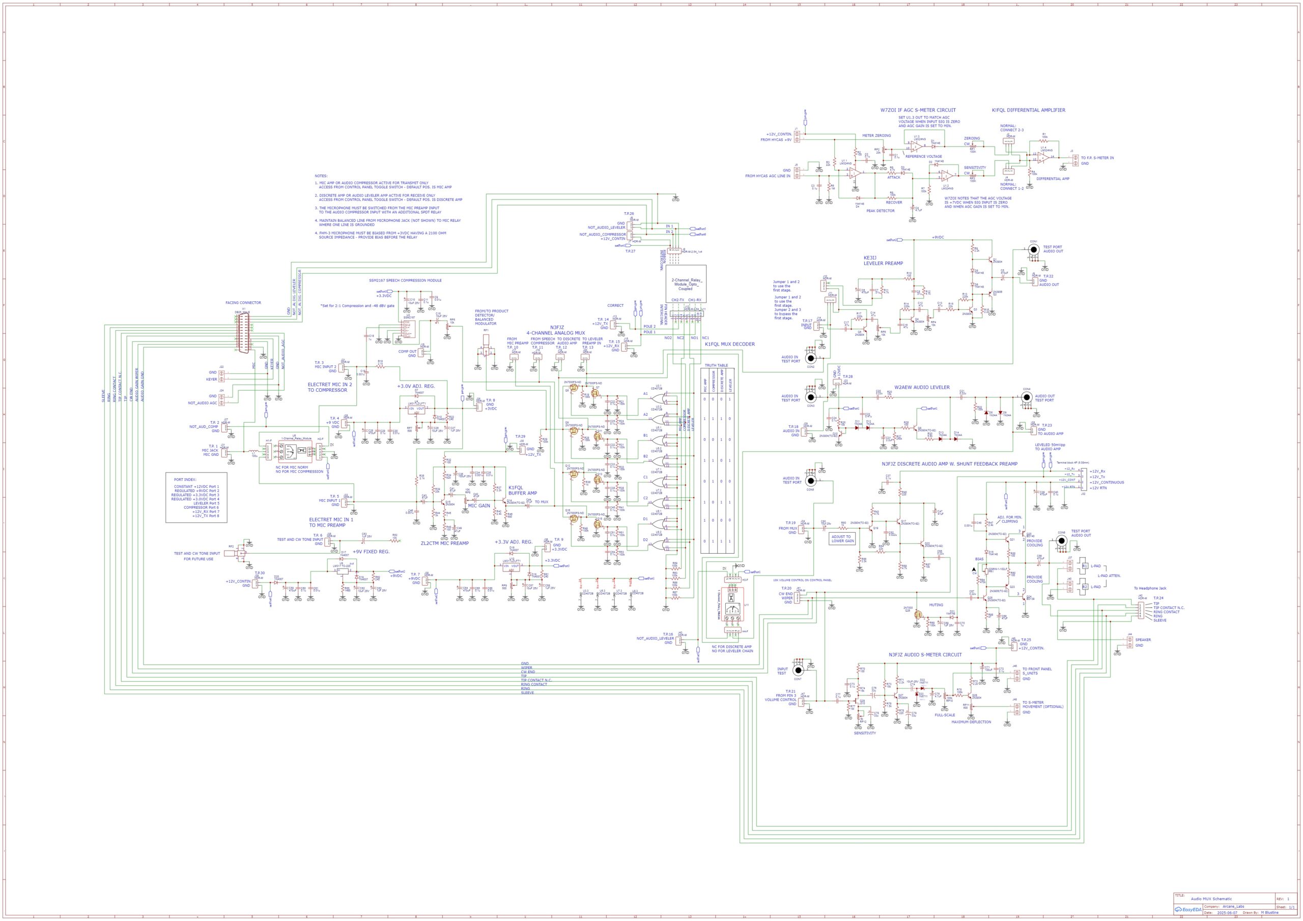
Figure 1. Audio Processor Schematic Diagram. The audio processor contains circuits from multiple sources. The CMOS MUX decoder is the work of the author. Test points on the schematic are numerous. Please click on the figure to open it in a new window.
Assembled Printed Circuit Board
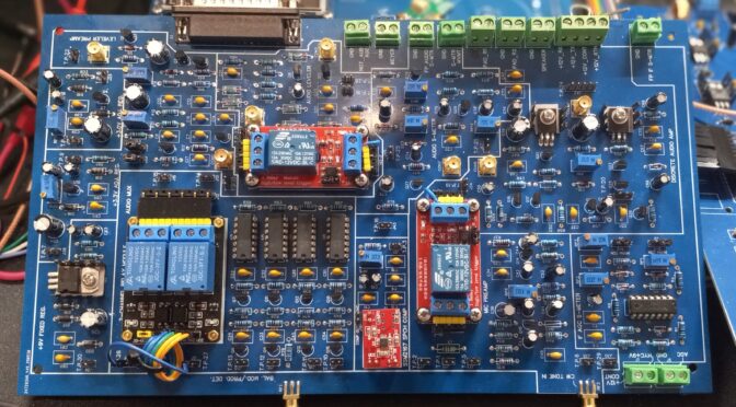
A photo of the populated circuit board is provided in Figure 2. The figure may be opened in a new window by clicking on it. The hardwiring corrections to two of the relays are visible in the photo as blue wires.
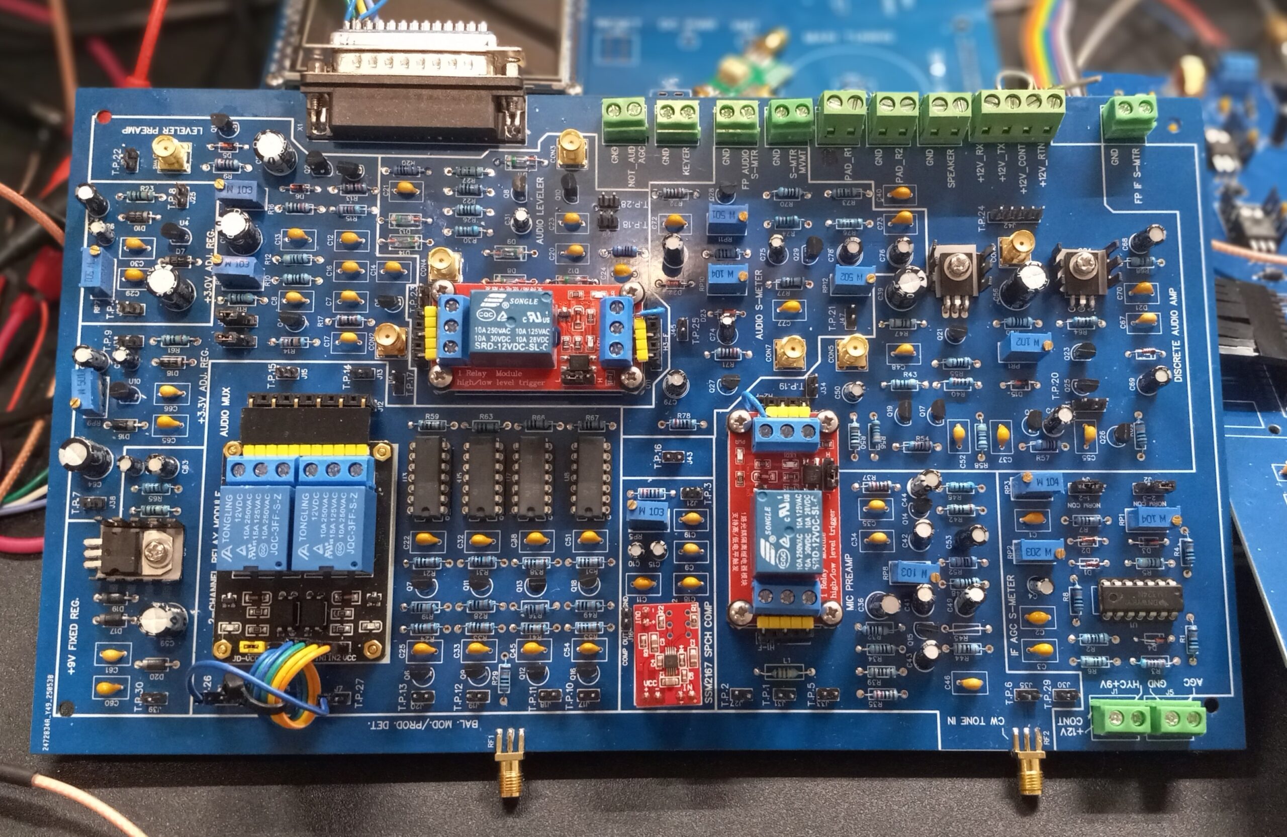 Figure 2. Audio Processor PCB. This assembly provides all of the receive and transmit audio functions. All of the audio functions described in this paper have been delineated with white lines on the PCB. A 4-channel audio MUX routes microphone audio to the balanced modulator on transmit and product detector audio toward the loudspeaker on receive. Numerous headers and SMA connectors for use as test points are visible on the PCB. The tiny, orange SSM-2167 audio compressor module is visible in the foreground. Please click on the figure to open it in a new window.
References
[1] Blustine, Martin, N1FD, June 9, 2025. https://www.n1fd.org/2025/06/09/audio-multiplexer/
[4] Ibid.
[5] Blustine, Martin, N1FD, Op. cit.
[6] http://www.remmepark.com/circuit6040/ZX-SSB-II/zx_ssb_ii.html#140
[7] Andersen, Rich, KE3IJ, SK. https://web.archive.org/web/20210430124905/http://www.ke3ij.com/radios.htm
[8] Wolke, Alan, W2AEW. https://www.youtube.com/watch?v=1h0FZJYXQ_w
[9] Scott, Rick, N3FJZ, from Elenco MODEL AM/FM-108TK Radio Kit (obsolete), and multiple sources. http://www.remmepark.com/circuit6040/ZX-SSB-II/images/(140)_ZX-SSB-II_Audio_Mic_Amp.png. Shunt feedback preamplifier, Cf. https://pe2bz.philpem.me.uk/Comm/-%20-%20Misc/-%20Amp/Info-901-AmpTutorial/BroadBand/broad-band-amplifiers.htm, and https://people.engr.tamu.edu/spalermo/ecen326/lab10_2022.pdf
_ZX-SSB-II_Audio_Mic_Amp.png)
[10] Scott, Rick, N3FJZ. http://www.remmepark.com/circuit6040/ZX-SSB-II/images/(130)_ZX-SSB-II_S-Meter.png
_ZX-SSB-II_S-Meter.png)
[11] Hayward, Wes, W7ZOI, Application Hints for the Hybrid Cascode IF Amplifier. Revision date, January 2, 2008. https://w7zoi.net/hycas-apps.html
[12] Morris, Charlie, ZL2CTM. Numerous examples of MIC preamps. http://zl2ctm.blogspot.com/
[13] Analog Devices, SSM2167. https://www.analog.com/media/en/technical-documentation/data-sheets/ssm2167.pdf. https://www.amazon.com/KOOBOOK-SSM2167-Microphone-Preamplifier-Compression/dp/B07TWC2MQB/ref=sr_1_1_pp?dib=eyJ2IjoiMSJ9.ZubOcTd_CDlGY_ee1TTfoKEIu2r-i5th4SaPrAup8TVjWHO7FFq2tZTr5_OhbHWH06ya_J4HGXPF3qqdxM04zbRivXMFwAx3jYu8SSuxcwaeKKtGDIVeQ1wWIqO-rmFwzWHRmq3l9rz_dMQGJ246KXRlh-iNw8B8FjCayydaB5VD6rU9pIfxRtmGU7bMZigOJin5rYlC4jZgTu7InLeO-BINALfH2AUZuXxMrS5i3dFZS3w3YISA5Qj9ta-XWV-q3grohV5oLRbsgTISbX4y0oL3GwgN9lbR2GbKTpYj0dA.F9CUiFt05wysKQAuP6VXs8-NfHc9FkD2Fnlqo07BZ0A&dib_tag=se&keywords=ssm2167&qid=1753643119&sr=8-1
Disclaimers:
The circuits included on this PCB were sourced from a number of authors. Only the 4-channel MUX decoder is original work. This is a somewhat advanced and expensive project, and some prior design and construction experience is recommended before taking on a project of this magnitude. This circuit design is provided for informational and educational purposes only and is supplied “as is” and without warranties of any kind, express, implied, or statutory. No representations or warranties are made regarding the accuracy, adequacy, completeness, legality, reliability, or usefulness of this information, either in isolation or in the aggregate. This circuit design may contain links to or information based on external sources or third-party content. Endorsement and responsibility for the accuracy or reliability of such third-party information or for the content of any linked websites are not taken.