Introduction
The Astron SS-30M is a popular metered, switching power supply rated at 30 A. It is commonly used to power 100W radios.
In spite of a ubiquitous changeover to LED illumination, Astron persisted in using incandescent illumination in their power supply meters until a few years ago.
This article discusses the replacement of incandescent bulbs in power supply metering with LED illumination.
Caution. Before proceeding with any disassembly, verify that the line cord has been unplugged from the power supply, or from the wall outlet. There is no isolation transformer in these switching supplies, so it is particularly dangerous. The cover is fastened with Torx screws to prevent tampering.
Procedure
Upon opening an older Astron SS-30M [1] power supply, it was discovered that the meter scale backlighting bulbs could not be replaced without meter disassembly. That got me thinking about whether I could install my own incandescent bulbs or LEDs to replace what was inside the meter housings.
When I checked the Astron website, I found that retrofit circuit boards [2] to backlight these meters were being offered for $3 each. The boards come complete with integral, white, surface-mounted LEDs, integral dropping resistors, and wiring pigtails. I immediately ordered two of them. This was a lot easier than retrofitting the old circuit boards with new LED bulbs and dropping resistors.
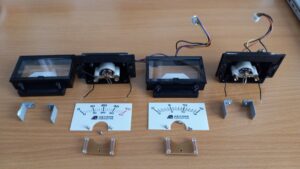
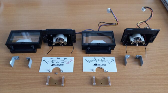
Meter disassembly is shown in Figure 1. The meters may be removed with their wiring harnesses and connectors intact. No desoldering is required to remove the meters from the next higher assembly. It is suggested that one of the harnesses and its mating connector be marked so that identification is easier during reassembly.
The meters are held to the power supply face with four spring clips (shown). These must be removed before the meters can be removed from the power supply face. Once the meters have been removed, the two screws that clamp each of the meters faces to the meter cases are removed (shown). Then, the meter faces may be swung upward to expose the meter movements. Care should be taken during this operation to remove any epoxy, RTV or plastic cement from the seam that holds the front face of the meter to the plastic meter housing. This may be done with a sharp blade. Once removed, each of the meter faces is set aside with its matching meter movement.

The next step is to remove the meter scale. It is fastened to the meter movement with two small screws. I grasped both sides of the meter scale with one hand while removing these screws with a jeweler’s screwdriver to prevent the scale from moving and damaging the meter needle. Once the meter scale has been removed, the internal meter movement and backlight bulbs are visible. The backlight bulb printed circuit board is held to the meter case with one small screw. This screw is removed with a jeweler’s screwdriver. Again, take care not to damage the meter needle.
Next, the printed circuit board is pulled up and away from the meter movement without touching the needle. Once out of the meter movement, the wires that power the board are snipped close to the old circuit board to leave the pigtails connected to the meter housing. The polarity of the lamp wiring is evident from the wire colors outside the meter case. In my supply, pink is used for the positive lead and black for the negative lead.
After stripping the insulation from the pigtails and tinning them, the new LED circuit boards were installed. A short length of very fine shrink tubing was slipped over each of the pigtails that had been soldered to the new circuit board at the factory. Next, the old pigtails were soldered to the new pigtails by paying close attention to the polarities. The pigtails on the retrofit are red and black.
Once soldered, the shrink tubing is slipped over each splice to prevent any chance of a short circuit between the meter circuit and the lighting circuit. Don’t heat gun the shrink tubing without protecting the meter movement. If the tubing is small enough, it may not be necessary to shrink the tubing at all.
Next, it was time to install the new circuit board in the rear meter housing. Care should be taken to protect the meter needle from the spliced leads when the board is installed with one screw. Once installed, any extra wire may be stuffed underneath the circuit board with a pair of long needle nose pliers.
Finally, the meter face is swung down over the rear meter housing, and the meter face is fastened to the rear meter housing with the original screws.
Once the meters have been reinstalled with the spring clips that hold the meters to the front panel, reconnect the meter wiring harnesses to the correct chassis connectors.
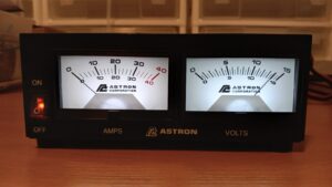
The next step is to fasten the top cover to the power supply with four Torx screws. Once closed up, an AC power cord may be connected and the supply may be powered up. If everything has been wired correctly and the wiring harnesses have been plugged into the correct sockets on the chassis, the meters should be illuminated with bright white light and the voltage meter should read what the supply was set to prior to disassembly. See Figure 2.

References:
[1] Astron Corporation, 9 Autry, Irvine, CA 92618. https://www.astroncorp.com/
[2] Ibid. https://www.astroncorp.com/product-page/led-backlight-circuit-board


There was a step omitted in the description for reassembly. After installing the new LED circuit boards and tucking the wires underneath, the meter scales have to be installed with two screws before fastening the meter face to the meter movement housing. M.B. 3/14/23